1)Be sure to disconnect both of main power supply and operating
power supply during maintenance or inspection.
2)Before maintenance or inspection, discharge the compressed air
from the air receiver tank and make sure that no pressure is left
in the compressor.
3)Disassemble the compressor after it has been cooled completely.
4)When disassembling the compressor, drain the cooling water from the compressor.
5) Clean up the outside so that dust may not enter into the unit.
6) Now overhauling of cylinder head
7)NOW we have left with cylinder block ,coolers,piston and connecting rod.
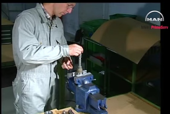
8) Removal of the valve procedure (1st stage) stuck to the cylinder head by lightly hitting it with handle of hammer
1) Entire air valve
(1) Wipe out the air valve outside (both 1st and 2nd valves) with a clean cloth, and check deposit of carbon or sticking of foreign matters. Check for of carbon and foreign matter
(2) If carbon or foreign matter is stuck, disassemble the valve and carefully clean it with soft cloth or brush.
2) Valve plate
(1) Push the valve plate from the valve seat side using a driver or steel bar (3mm dia.), and check abnormality of valve plate face, and action of spring. Put the driver in several place to check action of the valve plate. The valve plate will make stroke equivalent to valve lift.
(2) If the valve plate shows improper action, disassemble and clean it.
(3) If the valve plate is worn, replace it with new one.
3) Spring
(1) Disassemble the 1st stage side spring to check its damage or wear.
(2) Check the appearance of the 2nd stage side spring if there is no damage or wear.
(3) Replace the damaged or worn spring with new one.
SECOND STAGE VALVE PARTS AND DISASSEMBLY
SECOND STAGE SUCTION VALVE ASSEMBLY
SECOND STAGE VALVE ASSEMBLY IN COMPRESSOR
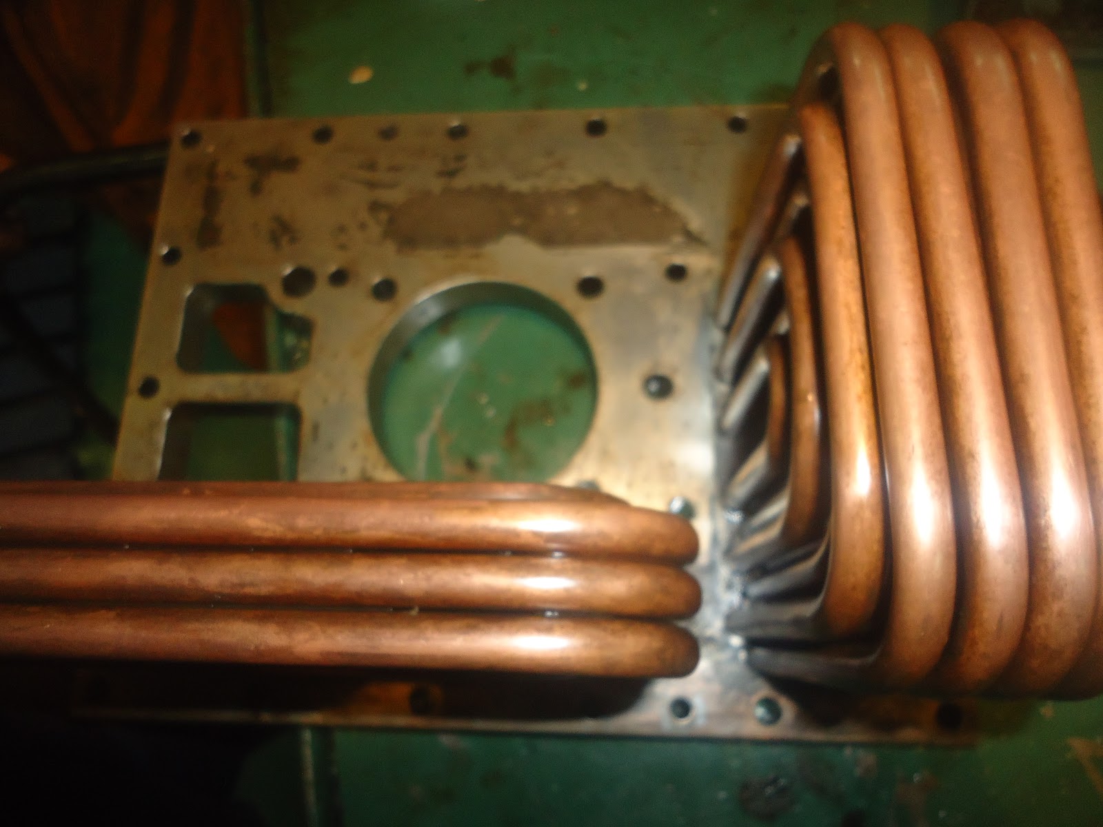
9)Cooler
Remove the cooler covers of both 1st and 2nd stages.
2) Water jacket
(1) Check if water dirt is stuck on the water jacket surface (both 1st and 2nd stages).
(2) When water dirt is stuck, clean the portion shown with the brush.
10) piston
* Remove the cylinder head.
* Remove the rod cap from the connecting rod.
* Screw in the piston removing tool at the top of piston, then extract the piston care fully so that the crank pin and the inside of the cylinder may not be scratched. At this time, connecting rod comes up together with piston assembly.
1) Outside of the piston
(1) Check that oil is properly applied.
(2) When quantity of oil applied is insufficient, first readjust the lubricator then replace it when it was found to be damaged or fault.
2) Piston ring
(1) Three piston rings are set on the 1st stage and three piston rings are set on the 2nd stage.
(2) Check direction of the ring (face and back) and extent of wear.
(3) If the direction of the ring is wrong, mount it correctly.
(4) Replace the worn piston ring.
(5) When setting piston rings into piston ring grooves, put the R-mark side of each ring upside and arrange the cut ends at interval of 120° so that all the cut ends will not be aligned.
(6) As each ring is narrow shaped and easily deforms, handle it with care.
3) Oil scraper ring
(1) Two oil scraper rings are set on piston skirt.
(2) Check direction of the ring (face and back) and extent of wear.
(3) If the direction of the ring is wrong, mount it correctly.
(4) Replace the worn scraper ring.
(5) When setting scraper rings into piston ring grooves, put the R-mark side of each ring upside and arrange the cut ends at interval of 180° so that the cut ends will not be aligned.
(6) As each ring is narrow shaped and easily deforms, handle it with care.
11) Oil system
1)Replace oil according to the operation time.
2)Drain the whole of oil while the compressor is kept warm at the interval of 50 and 100.
3)Thereafter replace the oil at intervals of 1000 hours.
4)Replace the oil filter at intervals of 2000 hours.
12)Oil screen
(1) Oil screen blocks coarse dirt.
2) Clean the oil screen when replacing the oil.
(3) Cover so that no dirt enters the oil screen, remove the stain with soft cloth, and wash with clean flushing oil.
(4) Replace the oil screen if it is broken.
13)Oil filter
(1) Oil filter filters minute dirt.
(2) Oil filter is cartridge type.
(3) Replace oil filler with a new one at every two times of replacement.
14)Oil pump
(1) Inspect oil pump every 8000 hours of operation.
2)After removing the bolts, replace the connecting piece suppressor. Shift the connecting piece toward the oil release valve body side using a minus
screwdriver and then remove the oil pump
3)Make sure that pump can be rotated smoothly by hand.
15) Lubricator (works for the lubrication of 1st stage cylinder)
(1) Replace the lubricator at every 8000 hours of operation.
(2) As quantity of oil supply has been adjusted to appropriate quantity before shipment, basically do not change it But when reconditioning becomes necessary ask for its details to compressor manufact
Others
1) Piping
(1) Check leak in the pipings.
2) Pressure switch
3) Magnetic valve
(1) Repeat ON/OFF of the operating power switch to check operation.
4) Suction filter
(1) Replace the suction filter at every 2000 hours of operation.
5) Pressure gauge
(1) Calibrate the pressure gauge periodically.
(2) If abnormality is detected, replace with now pressure gauge.
6) Safety valve
(1) Periodically check operation of the safety valve of 1st stage and 2nd stage.
7) Cooling water pump (for compressor with a cooling water pump)
(1) Check if water dirt is stuck.
(2) If water dirt is stuck, clean the pump using a brush.