Saturday, June 29, 2019

Procedure for launching of totally enclosed lifeboat

The procedure are as follows:

1.. Remove battery charging plug close drain plug remove overlashing wire rope fitted check painter rope if fitted .
2.go inside and start one battery, before entering the lifeboat ensure that forward and aft hook release lever are pointing to the green safe position .
3. Three  securing pin must take out two  each on forward and aft on cradle stopper and one pin  in break governor.
4.from outside just lift the brake Governor or deadman handle or holding brake or it can be done from inside the lifeboat also..

5.The boat along with cradle slides down till it comes to the embarkation deak
6. remove the gripe wire if fitted carryout pre-launch check
7.by pulling tricing pendant bring it alongside to the embarcation Deck
8. allow crew to enter the lifeboat and ensure all crew are starpped in.
9. now lower the lifeboat by the wire connected to the brake governor or from outside also it can be lowered lower the lifeboat until the keel is just above the water
10.instruct two crew one forward and one aft to remove the green handle locking pin from the hook.
11. lower the lifeboat by Coxwain  release handle .on contact with water ensuring the lifeboat is totally waterborne remove the safety pin from Coxwain release handle assembly confirm via inspection window that the hydrostatic interlock unit has operated successful in moving the emergency interlock handle to the open position that is in red area, lift the cocks when release handle up against the reaction of the return spring until the spigot pins are clear of the side plates lot then pull the handle back to its fullest and not proceed to sail away .
emergency release on load release procedure.
 in situation where the lifeboat is waterborne and the safety pins from the coxwain  release handle assembly has been removed but the hydrostatic interlock unit has failed to move the emergency interlock handle into the open position or red area the following process your must be adopted the procedure is same for the onload release where the lifeboat is not waterbourne.
1. break the inspection window glass to gain access to the emergency interlock handle and push it upward  and hold it in open position that is in red area.
2. lift the cockswain release handle up (against the reaction of the return spring) until the spigots pins are clear of the side plates slots then pull the handle back to its fullest extent .


12.release the painter release by release printer handle.
13. letting go 1. start engine  2.if in dangerous atmosphere open air supply in water spray valve 3. release painter when ready4. stay away from ship.
14. Final action 1. rescue any swimming survivor it safe to do so 2.when clear of vessels stream sea anchor 3. operate EPIRB and SART.

Friday, June 28, 2019

Generator and circuit protection (protection relay ,MCCB,MCB AND FUSE) in ship

PROTECTION RELAY;

Relay is a protective device which senses the faulty condition in a power circuit line and initiate the operation of the circuit breaker to isolate the fault. Apart from the rest of the healthy power system many form of electrical protection are available which are designed to protect the distribution system. protection relay are used to monitor overcurrent, over under voltage, overload, under or over frequency , Earth leakage and balance loading over temperature, reverse power etc.

No matter how well design and operation there is always the possibility of developing an electrical equipment fault, which can develop due to natural wear and tear in-correct operation and accidental damage.

Three reason why protection equipment is essential in electrical distribution system . 1 to disconnect the faulty equipment in order to maintain the power supply to the remaining healthy circuit .2 to prevent damage to equipment from thermal and magnetic force that occurs during short circuit and overload faults 3. three to protect Personnel from electrical shock.
Protection Scheme consists of circuit breaker, fuses, contractor. Relay detects the fault in circuit and then  initiate the trip action. Relay detect the faulty current and then signals the breaker to cut the supply of current to the faulty equipment.


The protection relays are as follows;

1.Overcurrent relay(initiates at 150% curent)- overcurrent is due to the short circuit faults in distribution circuit . 
The types include magnetic relay( embedded in ACB ,MCCB,MCB and initiates trip action in ACB of generator,MCCB,MCB of distribution circuits). Magnetic relay construction is similar to that of a domestic water metre or reverse power relay.

Relay is made up of light weight non-magnetic aluminium disc between two soft laminated iron core Electromagnets. the upper magnet is wound with voltage coil which is supplied from one phase and artificial neutral of generator output. The current coil connects to the same phase as the voltage in the upper electromagnet sense voltage coil has more number of turns so it has more inductive value .the current coil has less number of turns so less value of Inductive and less induced current that  lag less.
As we know current carrying conductor produces magnetic field so both upper and lower section produces magnetic field but induced current  in voltage coil lags more than current coil so magnetic field produces and upper section will be weaker than the lower section and both magnetic field will have a difference of 90 degree. When both field pass through the aluminium disc it produces Eddy current which makes the disc to rotate . Accessing current due to short circut causes rotation against the spring and moving contact so that the tripping circuit is closed.

2.OVERLOAD RELAY(initiates at 110%load) it can be due to mechanical overloading of motor and for ex if 1 generator is running and too many loads are given to the generator. The types of overload relay are
1.dashpot type(embedded in ACB): it allows preferential trip in running generator and slowly shutting off the non essential load if still overload in generator it trips the air circuit breaker of generator in 15 sec time delay.

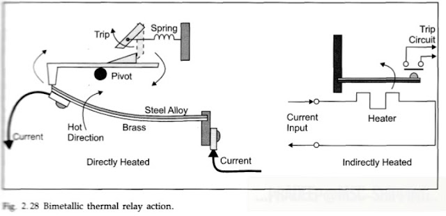
2.Thermal type;(embedded in MCB ,MCCB and contractor of motor etc)
3.electronic type overload relay; Magnetic type overload relay operate by sensing the strength of magnetic field produced by the current flowing to the motor .The greatest difference between the magnetic type and thermal type overload relay is that magnetic type is not sensitive to ambient temperature type overload relay are generally used in areas that exhibit extreme changes in ambient temperature. electronic overload relay employs a current transformer to sense the motor current the conductor passes through the core of a toroid  Transformer. it induces voltage in directly proportional to the amount of current flows to the motor .The voltage induced into a toroid transformer is transmitted through a  connected electronic interface that provides a time delay necessary to to permit  the motor to start.


3.under voltage relay: (embedded in ACB ,all motor stator in contractor with setting 0.8 of rated voltage)-- undervoltage release mechanism is fitted to all generator breaker its main function is to trip the breaker when a severe voltage dip around 50% occurs this is achieved by lifting the mechanical latch which keeps the contact close to allow the trip spring to function which opens the breaker . The UV release on a generator circuit breaker also prevent it being closed when the generator voltage is very low or absent .UV relay may be magnetic or electronic. It also provide backup protection to short circuit protection as an example suppose during generator paralleling procedure your attempt was made to close the wrong circuit breaker if the circuit breaker was close the dead generator would be the equivalent of a short circuit fault on the bus bar and cause a blackout. The under voltage relay prevent the closure of circuit breaker of the Dead generator. The UV protection is also provided for motor starters the starter contractor thermally provide this protection as it drops out when the supply voltage is lost or is drastically reduced it prevent motor from restarting automatically when power is restored after blackout.


4.Negative phase sequence relay

5.earth leakage relay


6.under and over frequency relay.


So all this relay will send a tripping current to circuit breaker to open the contacts and disconnect  the faulty generator or circuit.


Various type of circuit breaker closing  mechanism may be fitted:-


1.Independent  manual spring used in mcb and mccb

2.motor driven stored charge spring: used in ACB -closing spring is charged by a motor gearbox unit spring recharging is automatic following closure of a breaker which is initiated by a push button this may be a direct mechanical release of the charged spring or more usually it will be released electrically that is a solenoid latch.


Now lets talk about circuit breaker and see its different type practically;

1.MCB :- they are small air circuit breaker fitted in moulded plastic covers they have current rating of 5- 200A and generally thermal over current and magnetic short circuit protection. They have very limited breaking capacity up to 3000 ampere and are commercially used in final distribution board instead of fuses.

2.MCCB:- used in industrial as well as commercial mccb rating is up 1000A with breaking capacity of 210 KA- 100KA. There are many functions such as magnetic overcurrent  trip function, thermal overload trip function ,undervoltage trip function, under frequency trip function etc they are small compact air circuit breaker fitted in a molded plastic case they have lower normal current rating 50-1500 ampere then main breaker and lower breaking capacity they usually have an adjustable thermal overcurrent setting and an adjustable overcurrent trip for short circuit protection built into  the case and undervoltage trip coil may also be included within the case . Operation to close is usually by hand operated Lever but motor charge spring closing can also be used . Mccb are reliable trouble free and require negligible maintenance . If the breaker operates in the on position for long period it should be tripped and close the few times to free the mechanism and clean the contacts.


3.AIR CIRCUIT BREAKER:- they have many trip function like magnetic type overcurrent relay trip, dashpot type overload trip, under voltage trip, reverse power trip ,low and high frequency trip etc.


Wednesday, June 26, 2019

NPSH in pump marine

1.DEF;The margin of pressure over vapor pressure, at the pump suction nozzle, is Net Positive Suction Head (NPSH). NPSH is the difference between suction pressure (stagnation) and vapor pressure.    

2.SOME POINTS; If a liquid to be pump is in a tank which is open to atmosphere and it is also at a height above the pump the liquid flow into the pump because of its head in due to the effect of atmospheric pressure on its surface. The pump in this case only adds to the energy of the system .
When a open tank containing the liquid to be transferred is at a lower level than the pump, the energy required to bring the liquid to the pump is provided by atmospheric pressure on its surface but the pump must create the drop in pressure which makes the atmospheric pressure effective.

 A discussion of the relevant features of the suction side of a pumping system must include not only the height of the liquid surface above or below the pump and the effect of atmospheric pressure but also the effect of a vacuum or zero pressure on the liquid surface, Vapour pressure and the characteristic of the Suction pipe. Liquid flow through a pipe  is impeded by friction over its length by valves or other restriction and by changes of direction.

 On the suction side the drop in pressure that can be produced by a pump is limited to that of and almost perfect vaccum  . Where comes on the discharge side there is theoretically , no limit to the height through which a liquid can be raised . 

If the pump is below the liquid level then HS will be positive if it is above the liquid level HS will be negative. Every liquid has a pressure at which it will vaporize and this pressure varies with temperature . If the combination of pressure and temperature  in the suction pipe is such that the vaporization occurs,  the efficiency of the pump deteriorate, and a condition can be reached where the pump will will cease to function. The vapour pressure is thus usually shown as a suction head loss in the equation.
              
3.NOW NPSH-As we know that 1 bar is equal to 10.3 metre theoretically it means any pump can lift water upto 10.3 metre but practically it won't because of the losses.

-(P_a+h)-(losses)= pressure at the eye of the impeller

Where p_a is atmospheric pressure and h is the depth of liquid in a tank
Now,
-(P_a+h)-( h_s+ vapour loss+ friction loss)= pressure at the eye of the impeller
Where h_s is height from tank surface to pump

So the final equation that you already see above

-(P_a+h)- (h_s + frictional losses +vapour losses)=NPSH

Under any given condition losses should not be more than the available head ,till the time above equation is positive pump  can easily take suction and when equation becomes zero that was the condition of cavitation and when equation becomes negative pump lose suction. If you use a centrifugal pump for pumping volatile liquid so at the time when pump takes suction there will be pressure drop in the suction line. So due to drop in pressure, vapour start forming. So now you have to reduce the vapour loss for that you need to submerge just the pump in a tank itself so now your equation becomes.

(P_a +h)- (-h_s+ vapour loss + friction loss)
Because h_s is height from tank surface to pump and pump is below the tank surface so negative sign in h_s .
So it means suction lift is added to the equation and your vapour loss becomes minimum.

Note: 1. Friction loss also increases too much if there was too much bend in the pipeline so due to increase in friction losses npsh will be reduced.


2. Just in case you have the pump in which vapour loss and friction loss is constant then in that case how to increase npsh for that you have to deal around h_s .


3. If we are pumping a liquid from a cargo tank then the value of the head(h) keeps on decreasing which means your npsh keeps on decreasing, so this was the only reason that at the time of stripping ,we throttle the discharge valve to reduce the frictional losses .With  throttled discharge valve you reduce the flow rate and hence the velocity decreases and we know that frictional losses is directly proportional to velocity.


4. Basically there will be the two important terms NPSH Required and NPSH available. Npsh required means that what you required and it is design concept and npsh available means that what is available to you, and That depends on the place where you are going to install the pump. If the npsh available is less than npsh required then the pump will loose suction. Now you have to find out why your npsh available is less .


There can be many reason for that like;
 1. Frictional losses too much
 2. Vapour lock in the pump
 3. Suction lift too high i.e h_s value is more
 4. The water that you are going to pump is too hot i.e vapour loss.
 5. If you throttle the suction side then frictional losses becomes too high that is hundred percent chance of Cavitation.

5. Every big pump in engine room  is kept at bottom platform to get a high h_s so that the NPSH is positive and pump will not loose suction.

Tuesday, June 25, 2019

Procedure to start a purifier in ship?

Starting the purifier:

1. Ensure the lines are set and respective walls are open usually the lines are set from settling tank to service tank.
2. Check the  oil level in sump.
3. Open operating water valve  to purifier and sludging  valve to sludge tank
4. Start the purifier feed pump with the three way circulation valve in a position leading to settling tank.
5. Open the steam to the heater slightly ensuring the drains are open so that the condenser drains close the drain once team appears.
6. After temperature is reached click on separator in panel.
7. Check for vibration and wait till RPM reachest 8000 RPM.
8. Open the bowl closing water which closes the bowl.
9. Now displacement water is added. The displacement water will push the oil towards the disc stack. After a calculated time for displacement water addition is stopped.
10. The opening water is given and the seperator discharges.
11. After the discharge,sealing water is added to the seperator bowl  till the water comes out of the waste water outlet.
12. Once the water overflows through the waste water outlet stop the sealing water.
13. Now the bowl opening water is given the seperator discharges ,the waste left in system is discharged.
14. Open the three way circulation valve such that the dirty oil feed is fed into the purifier.
15. Wait for the back pressure to built up
16. Check for overflowing of dirty oil through waste water outlet and sludge port
17. Now adjust the back pressure throughout to a value as a specified in the manual.
18. Now purifier is put into operation changed over the clean oil filling valve to service time.

OVERHAULING OF CYLINDER UNIT of auxiliary engine IN SHIP

THE PROCEDURE FOR DISMANTLING OF CYLINDER UNIT FROM THE ENGINE ARE AS FOLLOWS: 1.Safety precautions -Stopped engine -Shut...