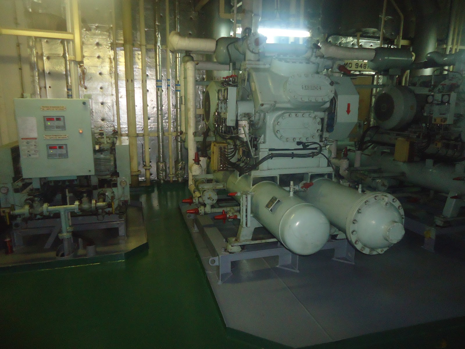
AIR CONDITIONING PLANT/CENTRAL COOLING on my SHIP with line LINE DIAGRAM . SHOWING various COMPONENTS/PARTS in detail.
Good ventilation is vital to the health and well-being of those on board ship
and the general requirements for ventilation, formulated before the universal
installation of air conditioning systems, still apply.[Heating, always necessary
for, the colder areas of the world, has in the past been provided by local
radiators or by heating coils incorporated with ventilation units. With
extremes of low temperature, these primitive methods of heating. increased the
capacity of the air to absorb moisture and caused excessive evaporation with
discomfort to crew and passengers due to drying of the nasal passages, throat
and sking. Air conditioning is based
accommodation and incorporates heating with any necessary humidification
and importantly, cooling with de-humidification as necessary. Comfortable
conditions depend on the temperature and humidity but are also sensitive to air
movement, air freshness and purity.


Mixing Section with dampers for manual or motorized operation. The mixing section is used for mix the fresh air from outside with return air coming from the accommodation. With 48.5 % return air.
2 dampers are present one damper with manual operation for fresh air and other damper for manual operation for return air.
Filter Section placed at the suction side, just at the mixing box or fresh air intake. The filter itself is a stainless zigzag-shaped frame with
a polyamide filter mat. After removal of the service door the filter can easily be drawn out for removal and replacing of the filter mat.
Heating Section for steam, electricity, hot water or thermal oil. Steam and water coils are constructed with aluminium fins on seamless copper tubes. Thermal oil heaters are made of steel pipes with steel fins heating section with steam 4.0bar, incl. of automatic controls type MONOSTAT.
Humidifying Section with spray nozzles for steam or water. Humidifying section with steam
automatic controlled and 1 - Drip pan with drain.
Cooling Section for direct expansion of Freon or for chilled water. The coil consists of copper tubes and aluminium fins.cooling section with freon R-404A incl. of 2 thermal
expansion valve with 1 - Drip pan with drain.
Water Eliminator Section placed just after the cooling section to prevent condensation water drops from the air cooler continuing to the fan section.
Fan Section containing a centrifugal fan with double inlet, V-belt driven. The fan unit is mounted on anti-vibration mountings and provided with flexible connection.
OPERATION OF PLANT


1)The capacity regulation of the compressor is controlled by the suction pressure based on the air inlet temperature of the air handling unit.
A pressure controls, type KP-1, in the suction line control the engagement and disengagement of the compressor cylinders by means of the three-way solenoid valves.

2)A liquid separator is mounted between air cooler and compressor.
The function of this liquid separator is accumulate a periodical excess of R-404A liquid (and oil, if any) leaving the air cooler in liquid state. From the liquid separator the possible excess of R-404A liquid will gasify and be sucked back to the compressor, together with
small quantities of oil, until the liquid separator has been emptied again
3)A liquid cooler is provided to compensate for the pressure drop in the long liquid line between compressor and air cooler. The liquid cooler is to be placed as close to the compressor as possible, and the object
of it is to subcool the liquid to prevent "flash gas" from arising at
the expansion valves and cause incorrect regulation of these.
The liquid cooler is equipped with a thermostatic expansion valve
governed by the superheat in the suction line.
4)Four solenoid valve is placed in the liquid line before the air cooler,and two electric sensor is placed on the mixing section at A.H.U. When the electric sensor reaches the set point, it will give an impulse to the solenoid valves to shut off the liquid supply to the air cooler, and the low pressure control will then stop the compressor.
Safety Devices
The operation of the compressor is controlled by the following safety
pressure controls :
- High/Low pressure - breaking in case of too high & low pressure in the refrigerating system, e.g. by failing supply of cooling water.
- Oil pressure switch-, breaking in case of failing Oil pressure in the lubrication oil system
- High temperature control KP 98, for oil and gas, breaking in case of too high gas temperature in the discharge line.
- Low temperature control for gas-breaking in case of too low gas temperature in the suction line
PARTICULARS OF MACHINERY
CONDENSING UNIT (2 sets/ship)
(2 sets x 100% CAPACITY)
Consists of compressor, condenser, drier, stop valve etc., built together on a common frame - complete with connections for refrigerant.
The unit consists of:
1.ONE-STAGE R-404A COMPRESSOR
Pressure lubricated, marine type.
Specification:
Number of cylinders -8
Bore 100mm
Stroke 8..0mm
Speed-1328 rpm
accessoriesa)Safety valve-1set/compressor
b)Stop valves on suction and discharge line-2sets/compressor
c)Panel with pressure gauges -1set/compressor
d)Low/high pressure control-1set /compressor
e)Oil differential control- 1set/compressor
f)Suction filter -1set/compressor
g)Oil filter -1set/compressor
h)Solenoid valve for capacity regulation-3set/compressor
i)Pressure switch for capacity regulation-1set/compressor
j)Electric heating element in crankcase -1set/compressor
k)3-way valves for gauge -.2set/compressor
L)Junction box, built in type on the condensing unit -1set.
2.MARINE CONDENSER --1set/compressor
Type : Horizontal shell-and-tube type
Materials:
#Tubes -cupper
#Tube plates-steel
#Shell -steel
#End covers -Steel with tar-epoxy surface coat.
accessories#Safety valve-1set/compressor
#Purging valve-1set/compressor
#Sight glass-1set/compressor
3.MARINE RECEIVER, 210 litres 1set/unit
Accessories :
#Safety valve-1set/condensor
#Purging valve- 1set/condensor
#Sight glass -1set/condensor
4.REFRIGERANT DRIER--1 set/unit
Drier core-4 e.u
Accessories:
#R-404A stop valve-2 sets/unit
#R-404A charging valve -1set/unit
#Sight glass -1set/unit
#R-404A by-pass valve-1set /unit.
OTHER ITEMS ARE
a)DUCT THERMOSTAT--2sets/ship To be placed in the fresh air intake.
b)SOLENOID VALVE-2sets
c)FILTER
d)THERMOMETER WITH POCKET for suction of air cooler
e)STOP VALVE
f)PRESSURE GAUGE for Fresh water inlet
g) THERMOMETER WITH POCKET
for Fresh water inlet and outlet
h) PRESSURE SWITCH for fresh water
i) LIQUID SEPERATOR -2 sets/ship
j) LIQUID COOLER -2sets
k) STOP VALVE -4sets/ship
l) EXPANSION VALVE TYPE -2s.e.ts/ship
m) SOLENOID VALVE TYPE
n) SWITCHBOARD for compressor
o) SWITCHBOARD for AHU fan .
ADJUSTING PRESSURE AND TEMPERATURE FOR COMPRESSORS
1.Pressure control
High pressure
cut out -22.0. bar
·cut in -manual reset
2.Low pressure
·cut out -4.2bar
·cut in-5.4 bar
3Oil pressure control
#cut out -3.5bar
#cut in -manual reset
#time delay -60s.ec.
4.High temp. Control :
Discharge temp. : ·cut out -105℃
Oil temp. : ·cut in-80.℃..
5.Capacity control
a)Pressure control KP 1 ( 50% capacity cut in ) :
#cut out - 5.0 bar
#cut in-6.0 bar
b)Pressure control KP 1 ( 75% capacity cut in ) :
#cut out- 5.4 bar
#cut in -6.4 bar
c)Pressure control KP 1 ( 100% capacity cut in ) :
#cut out -5.9 bar
#cut in- 6.9 bar
6. Thermostst RT 140 :
#(NO.1) .cut out - 20 ℃
.cut in-23 ℃
# (NO.2) .cut out-29 ℃
.cut in- 32 ℃
7.Cooling water low pressure control :
·cut out -0.4 bar
·cut in-0.8bar

No comments:
Post a Comment