ALL ABOUT FIRE FIGHTING APPLAINCE ON SHIP
Class of Fire explain?
ON CLASS A (CARBONANCEOUS)= USE WATER MOSTLY
ON CLASS B ( OIL FIRE ) = USE FOAM, D.C.P.,CO2
ON CLASS C ( GAS, CHEMICAL FIRE ) = USE D.C.P
ON CLASS D ( METAL FIRE ) = USE D.C.P
ON ELECTRICAL FIRE = USE D.C.P AND CO2
1. STARVATION: Cutting of FUEL.
2. SMOTHERING: Separating the FUEL from the OXIDANT.
3. COOLING: Lower the TEMPERATURE, usually with water.
4. INHIBITION or RETARDATION OF THE COMBUSTION REACTION: Removal of MOLECULAR Chain Reaction
=======================================================================================
PORTABLE FIRE EXTINGUISHER
Q 19: Explain in Detail about all Portable extinguisher (mostly surveyor asking about CO2 and D.C.P )with cross section of it.?
Q 19 a: Solas Regulation regarding portable extinguisher?
Q 19 b: Weekly, monthly and Yearly maintenance on it?
Q 19 c: Weighting of extinguisher? How you will do it?
Q 19 d: Marking on portable extinguisher?
Solas Regulation:

-Accommodation, Service space, and Control station shall be provided with P.F.E (portable fire exit of appropriate type and in sufficient number to the satisfaction of the Administration.
-Ship of 1000 GT and above have at least 5 P.F.E.
-Total weight shall not more than 23 Kg, and capacity of fluid not less 9 ltr and not more 13.5 ltr.
-One of the P.F.E intended for use in any space shall be stowed near the entrance to that space
-CO2 P.F.E shall not be use in Accommodation.
-P.F.E shall be situated ready to use at easily visible
-P.F.E shall be provided with Device which indicate whether they been used .Spare charge shall be provided for 100% of the first 10 exti. And 50% of the remaining P.F.E ,Capable of being recharge on board. But not more than 60 total spare charge are required.More P.F.E which cant recharge on board additional P.F.E of the same quantity, type, capacity shall Be provided lieu of spare charge.
WATER TYPE ( SODA ACID TYPE) P.F.E
Working principle on =COOLING effect
Use= Carbonaceous Type A fire
Safety= Relief hole and Safety pin
Body= Solid drawn steel and internally Zinc coated
Contain= CO2 74 mg ( it will be different as per weight and capacity of Cylinder) at 36 bar pressure and Water 9 ltr minimum.
Duration of working = 6 meter jet length for 60 second
Working
-carry exti. Nearby the fire. Bring Extinguisher Towards the fire.
Remove safety pin and strike plunger to pierce the CO2 cartridge
When it will pierce the pressure created on the upper part of the container and water from the jury Hutu dicharge tube will pass and thrown as a Jet spray.
Maintenance:

===============================================
MECHANICAL FOAM TYPE
Working principle on =SMOOTHERING effect
Use= Volatile petroleum, paint, oil Type A, B fire
Safety= Relief hole and Safety pin
Body= Solid drawn steel and internally Zinc coated
Contain=CO2 74 mg ( it will different as per weight and capacity of
cylinder) at 36 bar Pressure ,A.F.F.F = 97 % and WATER= 3%
Duration of working = 6 meter jet length for 60 second
Working
-Carry exti. Nearby the fire. Keep exti Towards the fire
Remove safety pin and strike plunger to pierce the CO2 Cartridge
When it will pierce the pressure created on the upper part of the container and water from the dip tube will pass and thrown as a Jet spray.
NOTE:
-do not allow foam to strike on the surface of burning liquid.
-Direct the foam to some nearly vertical surface so that the foam runs down the side and blanket the liquid
-If you dont found any vertical surface than it is advisable to keep a distance such that the discharge from the extinguisher will fall gently on the liquid surface.
-Use same manufacture for refills and if you using pre-mix type fluid than DON’T INCREASE or DECREASE the proportion of the fluid bcoz it will affect the efficiency of the extinguisher.
Maintenance:

========================================================================
CO2 TYPE

Working principle on =SMOOTHERING effect
Use= oil, electrical, petroleum product, gaseous
Substance under enclosed space, Type B
Safety= control valve or safety valve, pressure Relief device and Safety pin
Discharge hose= NON-conductive material
Body= Solid drawn steel and internally Zinc coated
Contain=CO2 4.5 kg ( it will different as per weight and capacity o
cylinder) at 53 bar pressure
Duration of working = 3 to 4 meter length for 2 second
Pressure tested= 210 kg/cm2 prior recharge
Recharge= only at shore and when weight reduced 10% and more
Storage= should be at least 750 mm above the Floor level, it should not placed where it likely to gain heat from surrounding equipment
Process.
Working
-Carry the extinguisher near the place of fire.
-Remove the safety pin
-Direct the hose at the base of fire, starting one edge and sweeping across the surface on burning material.
-When use in open air the operator should stand up the UP-WIND side of the fire
-Fire on electrical equipment , first SWITCH-OFF the current supply.
Maintenance:

================================================
DRY-CHEMICAL POWDER TYPE

-Working principle on =SMOOTHERING effect
-Use= oil, electrical, petroleum product, gaseous substance unde
Enclosed space, Type A,B,C,D and electrical also.
-Safety= Safety pin, Relief hole in picture it will not show the inner container but there will be Inner container for CO2 Cartridge bcoz Sodium Bicarbonate will Wet freeze when it will come in direct contact with CO2 bcoz CO2 is Cool gas.
-Body= Solid drawn steel and internally Zinc coated
-Contain= inner shell CO2 60 mg ( it will different as per weight
And capacity of cylinder)
-Outer shell: 4.5 kg of D.C.P powder
DCP powder contain mixture of
SODIUM BICARBONATE + MAGNESIUM STEARATE
NaHCO3+ Mg( C18 H35 O2)2
Duration of working = 3 to 4 meter length for 20 second
Pressure tested=35 kg/cm2 prior recharge once in 3 year
WORKING:
-Carry the extinguisher to the place of fire and keep it upright
-Remove the safety pin and strike plunger. CO2 will escape to main shell and push out powder in the foam of FOG
-When using outdoor the extinguisher operate upwind side of the fire for better range.
Maintenance:

NOTE: MAGNESIUM STEARATE use for the purpose that it will not allowed to choking effect in powder.
But if choking will be there remove and replace with fresh charge.
================================================
MARKING ON EXTINGUISHER: (as per FSS code
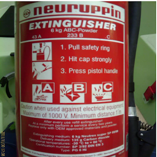
-Name of manufacture
-Type of fire for which the extinguisher suitable
-Quantity and Type of extinguishing medium.
-Approval detail of COnstruction for use and recharge
-Year of manufacture
-Temperature range over which the extinguisher will operate
-Test pressure
=======================================================================
SEMI-PORTABLE TYPE
SEMI PORTABLE EXTINGUISHERS :

-Types: CO2, Dry Chemical Powder & Mechanical foam
-Propellant: Externally fitted CO2 cartridge.
-Capacity: 55 liters / kg ( will be different
-Discharge Mechanism: 15 meters Hose-reel type
-Period of discharge duration: Maximum 3 minutes
-Head Assembly: Brass with tell - tale hole relief
system .
-CO2 cartridge operating lever equipped with safety Pin
-Maintenance: Weekly physical inspection & Annual complete servicing
-Location: CO2 adjacent to MSBD
DCP & Foam Boiler & Purifier Rooms
=======================================================================================
Explain Detector type? Working of it?
Regulation regarding detector?
location of it
HEAT DETECTOR
-location-Mainly in purifier room, near boiler platform, around M/E, A/E, incinerator etc
-Position:located on the overhead shall be minimum distance of 0.5 m away from bulkhead, except in corridor, lockers and stairways.
-Operate: operate before the temp exceeds 780 c but not until temp rise 540 c when the temp rise the those limit at a rate less than 1degree c per minute.
-Regulation required:
Max floor area per detector: 37m2
Max distance a part between centre: 9 m
Max distance away from bulkhead: 4.5 m
-Power supply: from MSB, ESB and TRANSITIONAL BATTERY.
TYPES OF HEAT DETECTOR
(1) Bimetal type: in this type there will be a bimetal strip, alarm and power supply connection are there in picture. In normal condition strip will not be bend but in case of fire occurs the strip will start
bend and it will touch the point and circuit will close , so current will flow through it and it will rise the alarm. It will take some time to come in natural position becoz of the property of bimetal.
Working range is from 55c to 160c .

(2) Fusible link type: the principle is the same once it will close the circuit it will rise the alarm. In this type there is fusible link connection together, when fire occurs it will disconnect and one of the connection will touch the plate and the circuit will close and alarm will sound.
Working range is from 55 c to 180 c.

(3) Rate of rise temp pneumatic type: in this type inside the casing of detector atmospheric air is there,when fire occurs the air will get expand due to heat and the upper part of detector have diaphragm
will get expand also and it will touch the plate and circuit will close and rise the alarm.
Working range is from 57 c to 82 c.

------------------------------------------------------------------------------------------------------------------------
SMOKE DETECTOR
location-w/h port and stbd, each deck -3 ,a/c room ,galley stairway,ECR, electrical workshop, purifier room ,comb boiler ,incinerator ,generator ,purifier.
Position:located on the overhead shall be minimum distance of 0.5 m away from bulkhead, except in corridor, lockers and stairways.
Operate:operate before smoke density exceed 12.5% obscuration per minute, but not until 2%.
Regulation required:
Max floor area per detector: 74
Max distance a part between centre: 11 m
Max distance away from bulkhead: 5.5 m
Power supply: from MSB, ESB and TRANSITIONAL BATTERY.
TYPES OF SMOKE DETECTOR

(1) Ionization type: in this type detector have positive and negative charge plate in container. A positive ions attracted to negative plate and vice versa. The movement of ions between the plates reduce
resistance of the air , so small current flow in the circuit. The small current is amplified so it can be readily monitored. In fire, smoke particle entering in chamber become attached and reduction of
ions flow will increase resistance and current falls down. Amplifier senses and monitored when i will below value it will give alarm.


(2) Light obscuration type: it work on photo electric cell principle, in normal condition light source will focus on P.E.C but when fire occurs and smoke will enter in container the reduction of light source on to the P.E.C will rise the alarm.

(3) Light scatter type: it work on the opposite to obstruction type, when light source will focus on the P.E.C it will give alarm.

===============================================
FIXED FIRE FIGHTING SYSTEM
CO2 FIXED FIRE FIGHTING SYSTEM
- Draw CO2 fixed system? Explain it?
-Regulation of this system
-Safety on this System? Explain about fire into E/R and P/R, -what is your action?
-Regulation Regarding CO2 Room? Safety in CO2 Room?
-Function of Master Valve
-Calculation Of CO2 bottle? What you mean by 0.56 in calculation?
-Weighting of CO2 bottle
-Maintenance on CO2 system?
-Principle of this system
SMOOTHERING and COOLING, reduceO2%
Regulation:

-First of all Solas regulation says that the ship which has MACHINARY SPACE of category A class 500m3 and above volume required additional fixed fire fighting system requirement that 85 % of the CO2 gas is released into the space within 2 min of the actuating the system release.
-bottle are SOLID DRAWN steel, hydraulically tested @ 228 bar.
-bottle should not stored where the temp exceed 55degree c.
-bottle pressure normally about 52 bar and it will varies with temp.
-bottle content are checked by RADIO ACTIVE ISOTOPE GUN level indicator or WEIGHTING.
-CO2 bottle head assembly the Bursting Disc are designed to rupture @ 177 bar produced by temp about 63 c.
-syphon tube in bottle ensure that liquid is discharged from the bottles.Without syphon tube the CO2 would evaporate from the surface giving a very slow discharge rate and taking latent heat, would cause the remaining CO2 in bottle to freeze.
-Once you CO2 is release it will reduce o2 in the space to less than 15 % to extinguish fire.
CO2 ROOM REGULATION
-The storage room should be used for no other purposes
- the storage space is located below deck, it should be located no more than one deck below the Open deck and should be directly accessible by a stairway or ladder from the open deck.
-Spaces which are located below deck or spaces where access from the open deck is not provided Should be fitted with a mechanical ventilation system designed to take exhaust air from the bottom
Of the space and should be sized to provide at least 6 air changes per hour
-Access doors should open outwards, and bulkheads and decks including doors and other means oF closing any opening therein, which form the boundaries between such rooms and adjacent enclosed spaces, should be gas tight
-Room temp should maintain below 55 degree c.
-Room should have a minimum clear height of 2.4 m to provide the mounting of manifold and weighting the cylinder
-if fixed extinguishing medium stored outside a protected space, it shall be stored in a room which is behind FWD collision bulkhead.
Safety on CO2 system
1.Trip switch: control cabinet have special trip switch for ventilation trip and sound CO2 alarm. As soon as you open cabinet it will trip ventilation and sound alarm.

2.Master valve: on main manifold line which is going to M/C space or Cargo space will have this valve.It will not allowed to release
CO2 in any of the space in case accidentally release.
3.Relief valve: it will located on at the end of manifold if manifold pressure will exceed the relief valve will lift up into ATM,
4.Safety pin : it will be provided into bottle head assembly, u can see into picture what I put just above.It will function like to dont accidental release of lever to operate and for manual operation you have to take it out to operate the lever.
5. Bursting disc: it will also into bottle head assembly .It will burst when the pressure into bottle exceed @ 177 bar along with the temp around the bottle reach 63 c.
6.Non-return check valve: as I mentioned into my
CO2line diagram, it will located between bottle and
Manifold.
Function of it is act as a non return and when you blow the system along with manifold it want allow to service air will pass through it, and if u have fire in Cargo hold or any one place where u need only few bottle to extinguish the fire, so once u operate system the manifold will fully pressurized but it want allow to open the another bottle after operating pilot cylinder.

7.leak alarm : the most of the surveyor want to hear this safety from you. As I saw you in my picture. It will located on the manifold. It will work @ 4 bar pressure, it like a pressure switch, if any of the CO2 bottle will leak so pressure into the manifold will be increase and as you know CO2 is stored @ 52 bar
pressure so a small leak will also create a high pressure in to manifold once the manifold pressure will reach @ 4 bar it will sound alarm, and by this safety switch you will get to know there is a leakage from any one bottle, but you dont know which one is it.
So now you have to found the leak bottle? Now the question is how
-Simple once u got alarm at least 2 person will go to outside the
CO2 room
-Start the ventilation and stay outside for some time
-Carry proper communication equipment with you
-Now after some time the space will be properly ventilated, go inside the room.
-Now the main thing how u can identify?
-So start from the first bottle by physical touch by your hand, if any of the bottle leak the bottle is much cooler than the other.
-Mark on the bottle and check another
-After u finished all of them, u can come to know how many of them is leak pipe work solid drawn mild steel & galvanized to protect against corrosion.
Safety in CO2 room:
-Room is fully insulated
-Proper ventilation provided
-Room access door open outward
-room should not be use for any other purpose
-All near by compartment should be gas tight
Required CO2 cylinder calculation:
On my vessel I had
For E/R = 201 cylinder
For Purifier room = 7 cylinder
And Spare = 4 cylinder
SO,
Total = 212 cylinder
Cylinder pressure store = 58 bar
Approx weight = 120 kg /each cylinder and cylinder tare weight is approx= 72-80 kg
Design discharge time = 120 second
Actual discharge time = 107 s
Solas regulation to calculate no of cylinder
1.If the CO2 system is installed in the cargo spaces, the quantity of CO2 available should be sufficient enough to give at least a minimum of 30% of the total volume of the largest space that
is protected by the CO2 system.
2.40% of the total volume of the largest machinery spaces that is protected by the CO2 system.The volume should exclude that part of the casing where the horizontal area of the casing
40% or less then the horizontal area of the space taken into consideration and measured midway, between tank top and lowest part of casing).
3. 35% of the total volume of the largest machinery spaces that are protected by the CO2 system including the area covered by the casing.
It is also a requirement that 85% of the required quantity of gas should be released into the spaces within two minutes of evacuating the fire-affected space.
Formulae

WEIGHTING OF CO2 CYLINDER
1.As I shown in figure below there is beam scale assembly tool, it is a special tool for weighting
2 It contain adjustable hook, yoke, scale from 0 to 200 kg and a handle
3.And in second figure the way to take weighting of cylinder is mention.
4.First you loosen the securing strap from the cylinder as shown in fig 1.
5.Fit the yoke in the CO2 head assembly and also fit the adjustable hook on the crossbar as shown in Fig 2.
6. Now pull down the scale with the help of handle and lift the cylinder upto it will free from the Bottom contact.
7.Now slowly pull down the beam to 900 against hook and now you can take reading from the scale.
Note: ± 5 degree of beam angle is allowed for measuring the bottle.
Recharge is must necessary if there is 10% reduction in weight.
Maintenance or check on CO2 system:
Weekly:
-Inform bridge before going inside the CO2 room.
-start ventilation blowers first and room should be ventilated for some time.
-Go with a person with proper communication equipment.
-Check all cylinder are properly secured
-Check all the operating lever and there accessories are properly tight.
-Check clamping.
-Check valve actuator
-Flexible hose visually check and do leak test if required
Monthly
Working of CO2 system
-In E/R you also have hyper mist system so if you sure that it will help full to extinguish fire you can Operate it also, for that you no need to shut any system.
-so you all know that this system we can use only inside the enclosed space, in open space it will not work any more .
-So mainly it will be use in Machinery space or Engine room and Purifier room and Cargo hold.
-This system must be operated by Chief engineer or
2nd Engineer, these two person are responsible
for all operation for this system
Fire in E/R what is your action
-so you seen fire in any place in E/R, immediately rise the Fire Alarm from nearby place by breaking the glass with the use of hammer but in case if you dont found hammer what u will do? In that case remove your safety shoes and hit on the glass bcoz shoes have steel plate at fwd part so by using that u can easily break the glass.
-Now if you can able to recognized that which type of fire is there than use proper type of portable fire extinguisher ( if fire is not too big )or if u cant able to extinguish that fire than call chief engineer or any dek officer on Bridge. Inform about location and type of fire.
-Now if M/E is running than immediately slow down and stop the M/E.
-After the instruction given by C/E or Master to release
CO2 system so before you leave the E/R make Sure that all access from the E/R must be closed properly.
-Stop your running A/E and start E.G. and take on load. As you stop A/E all ventilation will also stop Just need to close flaps.
-Now all crew member except the one bridge watch keeper or any officer or master. All have to present at muster station for head counting
-After head counting done as per the muster list follow the duty.
-Regarding closing vents, doors, flaps, damper, quick closing valve for fuel line.
-Now start the Emergency Fire Pump to make boundary cooling for the E/R bulkhead continue.
-Now from the fire control station you can operate the
CO2 system.
-Make sure that all crew member are present, no one is missing.
-Open the cabinet with the help of key, as soon as you open it will cut the power supply for Ventilation fans and sound the CO2 release alarm in E/R.
-Now operate the pilot cylinder valve and master valve to release the CO2 as given
-keep continue boundary cooling and time to time check the temp of B/H.
ABOVE PICTURE WILL TELL YOU WHEN U OPEN CABINET THAN HOW THE VENTILATION SHUT AND
ALARM SOUND
Fire in PURIFIER ROOM what is your action?
-In P/R you also have hyper mist system so if you sure that it will help full to extinguish fire you can operate it also, for that you no need to shut any system. But if high then co2 to be flooded
-In this case as you found fire in P/R. immediately rise the Fire Alarm from nearby place by breaking the glass.
-Stop the purifier from outside of the room by using EMERGENCY STOP
-Now if you can able to recognized that which type of fire is there than use proper type of portable fire extinguisher ( if fire is not too big )
-close the P/R door. DoN’t forget to Close it
-If you cant able to extinguish that fire than immediately run
to inform the C/E and Deck Office on Bridge. Inform about location and type of fire.
-Shut the ventilation of the P/R from the MSB. And shut the flaps
-Shut the quick closing valve for fuel line only for the Purifier.
-Make boundary cooling for purifier room.
-C/E will be responsible to operate the CO2 system from the outside of the P/R or from Fire control Station
-Release the CO2 as per I mentioned above.
-Keep continue boundary cooling.
Prevention of Purifier Fire:
-lf the pipes leading to the separator are to be double sheathed; the reason for this is that if inner pipe leaks, then it will not spray all over the place but instead it will leak into outer pipe.
-drip trays should be provided below the purifier or separator, so that in case of oil spill the oil will wont flow and spread in the purifier room and contact with any hot material and catch fire.
-lf the pipes with flanges or connections are to be covered with anti spill tapes which can prevent spill from the flanges in case of a leakage.
-Fire fighting system such as water mist and CO2 system should be installed.
-Quick closing valves and remote stopping of pumps and purifier should be provided.
-Fire detection and alarm system are to be provided so that quick action can be taken.
=======================================================================================
SPRINKLER FIXED FIRE FIGHTING SYSTEM
Q 22: Expalin sprinkler fixed fire fighting system?
Q 22a:Regulation about it?
Q 22b: Can we use fire pump?
Q 22c: Draw sprinkler head and working range of it, and which liquid inside bulb?
-Working principle : Cooling
-SOLAS REGULATION


-Every cargo ship 2000 GT and above have fitted
M/C space 500 m3 in volume and above required additional fixed fire fighting system.
-It must have at least TWO source of power for the S/W pump, Alarm & Detection system and F.W.Pump.
-In Accomodation and service space the sprinkler shall come into operation within temp range from 90 c to 79 c except where high temp might be expected the operation temp may be increase by
Not more than 30 c above maximum deck head temp.
-Sprinkler shall be resistant to corrosion by marine atmosphere.
-Sprinkler system is divided into section, each section is permitted to contain not more than 200 Head.Each sprinkler head is sufficient to cover the areas of 16 m about. Sprinkler head are spaced not more than 4 m apart and 2 m from the vertical wall. Each sprinkler head capable of 100 litre/min discharge. It highest sprinkler head in the system is not less than 4.8 bar pressure.
-Each section of sprinkler shall be capable of being isolated by ONE STOP valve.
-Location of STOP valve outside of the associated section or in cabinet and clearly and permanently Indicated.
-Test valve shall be provided for testing the automatic alarm for each section of sprinklers by a Discharge of water equivalent to the operation of one sprinkler. The test valve for each section shall
be situated near the stop valve for that section
-Gauge indicating the pressure in the system shall be provided at each section stop valve and at acentral station
-This system is not to be fitted where NO risk of FIRE, such as Void Space,CO2 room, Public Toilet, etc.
-Paint locker room shall have sprinkler with designed 5 litre/m2 min connected to FIRE MAIN Pump of the ship.
-list or plan shall be displayed at each indicating unit showing the spaces covered and the location .If the zone in respect of each section. Suitable instructions for testing and maintenance shall be
Available
-The sprinkler system shall have a connection from the ship's fire main by way of a lockable screw Down non-return valve at the connection which will prevent a backflow from the sprinkler system to the fire main.
BULB OPERATING RATING

Orange : 57c
Red : 68 c
Yellow: 79c
Green : 93 c
Blue: 141 c
MAINTENANCE OF THIS SYSTEM
-Pressure tank level check and recharge
-Greasing of various valve
-Check alarm system.
-S/W pump testing by closing isolating valve and opening drain valve of pressure switch when the pump should start automatically.
-Drain whole system yearly or every 6 month.
Testing procedure:
-Close the section isolating valve, this will raise an alarm indicating zone isolation
-Now, open the test valve, if no water comes out, then it means the NR valve placed after the Section-isolating valve is not leaking.
- The test valve can be opened to create flow and cause the non return valve and exposing the annular groove which connects to a diaphragm alarm switch ( audible and visual ).FROM THE NON RETURN VALVE OF SECTIONAL VALVE TO THE QUORTZOID BULB OF SPRINKLER HEAD THERE IS ATMOSPHERIC AIR AND BELOW NON RETURN VALVE OF SECTIONAL VALVE THERE IS WATER. AS FIRE OCCURED IN ANY SECTION THE BULB WILL BLAST THE AIR WITHIN WILL ESCAPE IN THE ATMOSPHERE , SO DUE TO LESS PRESSURE IN THE LINE FROM NON RETURN VALVE OF SECTIONAL VALVE TO QUORTZOID BULB OF SPRINKLER HEAD , THE WATER WILL LIFT THE NON RETURN VALVE IN SECTIONAL VALVE AND THEN WILL GO IN LINE AND SPRAY IN THE SECTIONAL SPACE WHERE FIRE HAS OCCURED .

-All the above alarms will be indicated on the navigation bridge, E/R as well as in the Fire Control room. The alarm will also indicate the particular zone from where it has risen.
-If all the alarm conditions are satisfied, close all the testing valves, open the section-isolating valve ,Purge the sprinkler line by air and again keep the line pressurized.
-Check from the pressure gauge, that proper pressure has been maintained or not.
=======================================================================================
HYPERMIST ( LOCAL APPLICATION ) FIXED FIRE FIGHTING SYSTEM
- Explain about your ship another fixed fire fighting system into E/R?
- Regulation regarding Local fire fighting?
- Safety on Hypermist system?
- How it will activate?
Working principle: COOLING
SOLAS REGULATION:

-Cargo ship 2000 GT and above have this system.
-M/C space 500 m3 in volume and above required additional fixed fire fighting system.
-In periodically unattended M/C space have Manual and Auto release
-In continue manned it have only manual release.
-It will protect are without the engine shutdown, personnel evacuation or sealing of space.
-Around M/E,A/E
-Boiler platform
-Purifier room
-Incinerator area
-Activation shall give a visual and audible alarm in the protected space.
Working;

-It will get activate only when TWO detector will get activate, than and than only.
-Once it will activate it will send a signal to fire alarm panel.
-Room fire alarm panel sense the ZONE of fire and it will send signal to Hypermist control panel
-H.M. control panel send signal to High pressure pump ( Plunger type reciprocating pump ) starter And also solenoid operating valve according to Zone of fire capacity of pump: 200 litre/min @ 70 bar pressure discharge
-At nozzle 12-20 litre/min @ 50 bar pressure discharge.
-It is very high water mist system which create a water fog which effectively puts out the fire while .Also providing a cooling effect.
Specialty of H.M Nozzle: its diffuser action in Nozzle drop in pressure at Nozzle throat will breaking he liquid particle into fine mist.

-The fire breathing process is based on three mechanism
1. cooling of the flame
2. reduction of the oxygen content by the displacement of the air by expansion of water vapour.
3.The diminuation of the radiant heat.
- The pressurized water in contact with the fire vaporized heat is converted into steam the this process lower the temperature . The water expands 1700 times taking the air away from the Fire.
-This system decreases water consumption then sprinkler system.
- it shall be supplying water for 30 minutes to avoid the reignition
-the capacity of the system shall be based on the largest of the protected area.
- Has smoke eliminating affect, the floating smoke particle being absorbed and settled by the fog.
- Hypermist switch should always be on auto mode.
Line test by blowing air
The whole piping system to be blown through with compressed air at a pressure of 7 bar. Check the free passage of air from the nozzle.
Alarm test
1.Detector sensor (2 test )
2.high and low level water alarms switch
3. electric source failure shall be tested .
TESTING
1. select the switch to manual position .
2.open the pin of solenoid valve and operate it.
3. From local start the pump.
4. Mist will start coming at the relevant nozzle.
5. stop the pump.
6. reset all the system.
AUTOMATIC RELEASE TEST
1. close the water suction valve.
2. disconnect the motor power cable.
3. activate both detector by UV lamp.
4. check the alarm of the main control panel visual and audible.
5.open the air flush valve
6. check the air release from the nozzle in that area.
7.push the stop button from local control panel.
8. put system reset back in Operation.
Reset the system
1.open the pump drain.
2. close the suction valve of water tank.
3. open the drain valve where tested .
4.After flushing with air and no water should come from nozzle only air should come. Now close the air valve.
5. put system back to normal position.
SAFETY
-High and low water alarm switch
-Detector sensor. ( TWO )
================================================
Draw Fire main system from your ship ? What is function of Isolation valve ? Regulation of Emergency fire pump and main fire pump ?Regulation of Fire hose and nozzle ? What is the Diameter of fire main line? Is there any Relief valve on line ? if yes so location of it, and if no than why ?
FIRE MAIN LINE
General Principles

-The fire main is a system consisting of sea water inlet(s), suction piping, fire pumps and a distributed Piping system supplying fire hydrants, hoses and nozzles located throughout the vessel.
-Its purpose is to provide a readily available source of water to any point throughout the vessel which can be used to combat a fire and is considered the backbone of the fire fighting systems onboard a vessel.
-Through the fire main system, the firefighter is provided with a reliable and versatile system capable of providing a number of different methods with which to engage a fire.
-Water can be supplied as a straight stream for combating deep seated fires, as a spray for combating combustible liquid fires where cooling and minimum agitation is desired or as a means to
protect personnel where cooling is the primary effect desired.
Extinguishing Capabilities of Water
Water primarily extinguishes a fire by the removal of heat. It absorbs heat more effectively than any other commonly used extinguishing agent due to its good thermal conductivity and its high latent heat of vaporization. it is most effective when it absorbs enough heat to raise its temperature to 100°C (212°F). Water absorbs additional heat as it goes through the transition from a liquid to vapor (i.e., steam). In the process of heating the water from normal temperatures, up through its conversion into
team, water absorbs approximately 2.6 kilo-joules of heat per gram(1117 BTU/lb) of water, which As a much higher heat absorption value than any other agent.This absorption of heat reduces the temperature of the burning vapors and also reduces the amount of vapor being generated by the cooling of the fuel surface
With adequate cooling, there is insufficient heat to maintain the self-supporting combustion process and the fire goes out .Water also has an important secondary effect. When it turns to steam, it expands about 1600 times in volume at atmospheric pressure. As a result, one cubic meter (cubic foot) of water can generate
p to 1600 cubic meters (cubic feet) of steam vapor.This great cloud of steam surrounds the fire, displacing the air that supplies oxygen for the Combustion process.
SOLAS REGULATION FOR FIRE PUMP
Sanitary,ballast, bilge GS pump may be accepted as fire pump provided that they are not normally used for pumping oil and that if they are subject to occasional Duty for the transfer or pumping of fuel oil suitable changeover arrangement are fitted.IN MY SHIP WE HAD 2 FIRE PUMP ,-FIRE AND GS PUMP &- FIRE AND BILGE PUMP with changeover arrangement.FOR BALLAST, 2 BALLAST PUMP AND 2 SEA WATER PUMP.

- Ship shall be provided with independently driven fire pump as follows
= cargo ship 1000 GRT and upwards at least 2
less than 10000 GRT at least two power driven pump
one which shall be independently driven.
- Arrangement of connection fire pump and their sources of power shall be as to ensure that if a fire is in any one Compartment would put all the pump out of action there shall be an alternative means consisting of an emergency fire pump with its source of power and connection located outside the space where the main fire pump for their source of Power located.
Location of space containing emergency fire pump the space containing emergency fire pump shall not be contiguous to the boundaries of the machinery space of category A or other space containing main fire pump no Direct Access shall be permitted between machinery space and space containing the emergency fire pump and its source of power ,when this is impracticable the administration accept and arrangement where the acess is by means of an air lock with the door of themachinery space being A60 class and other door being at least Steel gasket self closing and without any hold back arrangement ventilation arrangement to went if any smoke possibility
- Additional pump for cargo ship in addition in cargo ship where the other pump such as general service, bilge and ballast etc are fitted to ensure to provide 2.7 bar of pressure to the main fire at least by one pump .
-Capacity of fire pump at a pressure of 2.7 Bar by all fire pump. Each cell have a capacity not less than 80% of the total required capacity by the minimum number of required fire pump but in any case not less than 25 metre cube per hour and each from shall in any event be capable of supplying the Fireman with two required Jets of water .
Diameter of fire main- self sufficient for the effectiveness distribution of maximum required discharge from the two fire pump operating simultaneously or diameter need only to be sufficient for the discharge of 140 metre cube per hour .
Isolating valve and relief valve
-ISOLATING VALVE to separate section of fire main within the machinery spaces containing the main fire pump or pump from rest of the fire means. It be fitted in an easily accessible and runable position outside the machinery space.
- The main fire shall be so arranged that when the isolating valves are shut, all the hydrant on ship except those in machinery space can be supplied with water by another pump'
- For emergency fire pump the emergency fire pump at sea water inlet and suction and delivery pipe shall be located outside the machinery spaces.
- A valve shall be fitted to serve each fire hydrant so that any fire hose may be removed while the fire pump are in Operation. It is a screw down isolating valve.
- RELIEF VALVE shall be provided in conjunction with fire pump pump are capable of developing a pressure exceeding the design pressure of water service pipes hydrants and hoses. This valves are so placed and arranged adjusted as to prevent excessive pressure in any part of the Fire main system. Fire line is fitted with relief valve to prevent the damage of pipe in case the valve is fighting fire with the help of shore in dry Dock.
EMERGENCY FIRE PUMP REGULATION
Apart from Main Fire Pump, an Emergency Fire Pump is also provided on board a ship, that can be
Used in case of an emergency like CO2 flooding or when Main fire pumps are disfunctional
-Capacity being 40% of the total capacity of the Main Fire pumps, but in any case not less than 25m3/h for passenger ships of less than 1,000 gross tonnage and for cargo ships of 2,000 gross
tonnage and upwards; and 15m3/h for cargo ships of less than 2,000 gross tonnages
-The emergency fire pump has its own independent means of power source, which can be used to take over in case of main power failure.
-it has attached priming unit and should be capable of overcoming the suction head in the lightest segoing draft the vessel may encounter and in any condition of list and trim.
-if suction pining is passing through the space to be protected must be additionally reinforced with fire retarted material so that damage take place and supply of water ensured at all time.
-the regulation required that if motor emergency gen can be met by a self contained CI engine driven unit or a hydraulic driven unit.
-emergency fire pump with its source of power and connection located outside the space where the main fire pump for their source of Power located.
Location of space containing emergency fire pump the space containing emergency fire pump shall not be contiguous to the boundaries of the machinery space of category A or other space containing main fire pump no Direct Access shall be permitted between machinery space and space containing the emergency fire pump and its source of power ,when this is impracticable the administration accept and arrangement where the acess is by means of an air lock with the door of themachinery space being A60 class and other door being at least Steel gasket self closing and without any hold back arrangement ventilation arrangement to went if any smoke possibility
-Such units, their sea suctions, means of priming, sources of power supply, switchboards, electric Cables and hydraulic piping as appropriate, must not be in the compartment containing the main
ire pumps, but in a position not likely to be cut off by fire or smoke in that compartment and be at all times ,Such that the supply of water is ensured venting of Emergency fire pump room should be as far as possible from M/C space to avoid any
smoke from M/C space fire entering into that space.
-The pumps can be started from remote locations also.
Though sea water is the best mode of fighting fire, the main emergency fire fighting system can only be used on fires of Type A. However, in case of class B fires, if all modes for extinguishing fire fails,sea water from main emergency system can be used
fire main system is also be used for boundary cooling
-Performance criteria = 12 meter jets from 2 hydrants located farthest from each other.
REGULATION FOR HYDRANT , FIRE HOSES , NOZZLES.

All the hydrant outlets are provided with an isolating valve so as to isolate those valves which are Not in use.The fire hydrants are also provided with standard size flanges in order to attach hoses which have Nozzles attached to them. All hoses are provided with snap in connectors for easy and quick Engaging and disengaging operation.The nozzles attached to the hoses can be operated in two modes jet and spray, depending on The type of discharge required for extinguishing the fire.The nozzles can be adjusted according to the type of spray and flow required, which could be used Over the fire to cool it without spreading.The pumps are connected with the main sea water connection, having appropriate head to prevent
any type of suction problem.
HYDRANT
=Shall be such that atleast two jets of water not emanating from same hydrant -one of which shall be from a single length of hose ,may reach any part of the shape normally accessible to crew -or in which latter case the to two jet shall reach any part of the space is from a single length of hose.
=Further more such hydrant shall be positioned and near the eccess to the protected space.At least two fire hose nozzle can be fitted in a fire hydrant.
=In machinery space two hydrant shall be provided but near to entrance to that machinery space.
=above 6000GRT the min pressure is 2.7 bar. The max pressure at any hydrant shall not exceed that at which the effective control of a fire hose can be demonstrated.
=Fire Main System must have at least two independently driven fire pumps that can each deliver water at a continuous pitot tube pressure of at least 3.5 kilograms per square centimeter approximately 50 pounds per square inch) at least two fire hose nozzles that are connected to the highest two fire hydrants on the unit.Alternative designs that meet the pressure requirement of this paragraph will be considered for column stabilized and self-elevating units. pressure @ hydrant:
or passenger ships:
4,000 gross tonnage and upwards 0.40 N/m
less than 4,000 gross tonnage 0.30 N/m
or cargo ships
6,000 gross tonnage and upwards 0.27 N/m
less than 6,000 gross tonnage 0.25 N/m
the maximum pressure at any hydrant shall not exceed that at which the effective control of a fire hose can be demonstrated.
Fire Hoses and Nozzles
Fire Hoses:
=These are made from synthetic woven textiles, lined with rubber and PVC coated.
=They are strong and are not affected by oils, chemicals, extreme climates and mildew.
=These are generally 18 meter long and 64mm diameter and provided with couplings and Nozzle.
15 m for M/C space
20 m other space and open deck
25 m open deck with a max breadth in excess of 30 m
=They are conspicuously kept at designated positions near the hydrants, either rolled or flaked, in a Fire Hose Box.
=Testing annually @ 50% above working pressure, damaged and suspect hose must be removed.
=Working pressure 17 bar and testing pressure 24 bar.
Nozzles
=They should be of approved dual purpose type, i.e. spray and jet, also incorporating a shut-off. They Are kept with hoses in the Fire Hose Box.
=Nozzles shall be fitted above the bilges, tank tops and other areas over which oil fuel is liable to Spread and also above other specific fire hazards in the machinery spaces. Precautions shall be taken to prevent the nozzles from becoming clogged by impurities in the water by corrosion.
=The number and arrangement of the nozzles shall be to the satisfaction of the Administrator and Shall be such as to ensure an effective average distribution of water at least 5 litre/m2 /min in the Spaces to be protected
=Where increased application rates are considered necessary, these shall be to the satisfaction of the Administrator.
Size are 12 mm, 16 mm, 19 mm
For accommodation only 12 mm use
INTERNATIONAL SHORE CONNECTION


=International shore coupling solas chapter 2 .2 regulation 19 says for 500 GT and upward must have at least one ISC. The connection should be made of steel or other suitable material and shall be designed for 1 Newton per mm square services .
=The flange should have flat surfae on one side and another side should be permanently connected or attached to the coupling which can be easily fitted to ship hydrant and hose connection.
= the four bolts 16 mm 50 mm in length and 8 washers ,gasketed to be available so that the connection can be readily used in case of emergency situation.
=ISC shall be clearly marked
=The velocity of water supplied by the port or other ship to the effected ship should not exceed 5m/s in the the fire water distribution network.
= The fitting and joint must be suitable for working pressue of atleast 10.5 bar.
= inner dia -64mm
outer dia -178 mm
pitch circle dia-132mm
================================================================================================
EXPLAIN DECK FOAM FOR FIRE FIGHTING SYSTEM?
Deck foam for fire extinguishing
=Foam for fire protection purposes is an aggregate of air-filled bubbles formed from aqueous Solutions, and is lower in density than the lightest flammable liquids.
=It is mainly used to form a coherent floating blanket on flammable and combustible liquids to Prevent or to extinguish fires by excluding air and cooling the fuel. It also prevents re-ignition by suppressing formation of flammable vapors.
= It has the property of adhering to surfaces, providing a degree of exposure protection from adjacent Fires.
=Foam is used as a fire prevention, control, or extinguishing agent for flammable liquid in tanks of Processing areas
=Foam solution for these hazards may be supplied by fixed systems or portable foam generating Systems.
=The principal use of foam is to extinguish burning flammable or combustible liquid spills or tank fires by developing a coherent coolant blanket.
=Foam is the only permanent extinguishing agent used for fires of this type. Its application allows fire fighters to extinguish fires progressively.
=foam blanket covering a liquid surface is capable of preventing vapor transmission for some time, depending on its stability and thickness.
=Fuel spills may be rendered safe by foam blanketing. The blanket may be removed after a suitable period of time.
=Foam is used to diminish or halt the generation of flammable vapors from non-burning liquids or solids, and to cut off access to air for combustion.
=The water content of foam cools and diminishes oxygen by steam displacement.
=Foam is also used to fill cavities or enclosures where toxic or flammable gases may collect.
=Foam solutions are conductive and therefore not recommended to


Solas regulation for fixed foam fire fighting system
Class of Fire explain?
ON CLASS A (CARBONANCEOUS)= USE WATER MOSTLY
ON CLASS B ( OIL FIRE ) = USE FOAM, D.C.P.,CO2
ON CLASS C ( GAS, CHEMICAL FIRE ) = USE D.C.P
ON CLASS D ( METAL FIRE ) = USE D.C.P
ON ELECTRICAL FIRE = USE D.C.P AND CO2
1. STARVATION: Cutting of FUEL.
2. SMOTHERING: Separating the FUEL from the OXIDANT.
3. COOLING: Lower the TEMPERATURE, usually with water.
4. INHIBITION or RETARDATION OF THE COMBUSTION REACTION: Removal of MOLECULAR Chain Reaction
=======================================================================================
PORTABLE FIRE EXTINGUISHER
Q 19: Explain in Detail about all Portable extinguisher (mostly surveyor asking about CO2 and D.C.P )with cross section of it.?
Q 19 a: Solas Regulation regarding portable extinguisher?
Q 19 b: Weekly, monthly and Yearly maintenance on it?
Q 19 c: Weighting of extinguisher? How you will do it?
Q 19 d: Marking on portable extinguisher?
Solas Regulation:

-Accommodation, Service space, and Control station shall be provided with P.F.E (portable fire exit of appropriate type and in sufficient number to the satisfaction of the Administration.
-Ship of 1000 GT and above have at least 5 P.F.E.
-Total weight shall not more than 23 Kg, and capacity of fluid not less 9 ltr and not more 13.5 ltr.
-One of the P.F.E intended for use in any space shall be stowed near the entrance to that space
-CO2 P.F.E shall not be use in Accommodation.
-P.F.E shall be situated ready to use at easily visible
-P.F.E shall be provided with Device which indicate whether they been used .Spare charge shall be provided for 100% of the first 10 exti. And 50% of the remaining P.F.E ,Capable of being recharge on board. But not more than 60 total spare charge are required.More P.F.E which cant recharge on board additional P.F.E of the same quantity, type, capacity shall Be provided lieu of spare charge.
WATER TYPE ( SODA ACID TYPE) P.F.E
Working principle on =COOLING effect
Use= Carbonaceous Type A fire
Safety= Relief hole and Safety pin
Body= Solid drawn steel and internally Zinc coated
Contain= CO2 74 mg ( it will be different as per weight and capacity of Cylinder) at 36 bar pressure and Water 9 ltr minimum.
Duration of working = 6 meter jet length for 60 second
Working
-carry exti. Nearby the fire. Bring Extinguisher Towards the fire.
Remove safety pin and strike plunger to pierce the CO2 cartridge
When it will pierce the pressure created on the upper part of the container and water from the jury Hutu dicharge tube will pass and thrown as a Jet spray.
Maintenance:

===============================================
MECHANICAL FOAM TYPE
Working principle on =SMOOTHERING effect
Use= Volatile petroleum, paint, oil Type A, B fire
Safety= Relief hole and Safety pin
Body= Solid drawn steel and internally Zinc coated
Contain=CO2 74 mg ( it will different as per weight and capacity of
cylinder) at 36 bar Pressure ,A.F.F.F = 97 % and WATER= 3%
Duration of working = 6 meter jet length for 60 second
Working
-Carry exti. Nearby the fire. Keep exti Towards the fire
Remove safety pin and strike plunger to pierce the CO2 Cartridge
When it will pierce the pressure created on the upper part of the container and water from the dip tube will pass and thrown as a Jet spray.
NOTE:
-do not allow foam to strike on the surface of burning liquid.
-Direct the foam to some nearly vertical surface so that the foam runs down the side and blanket the liquid
-If you dont found any vertical surface than it is advisable to keep a distance such that the discharge from the extinguisher will fall gently on the liquid surface.
-Use same manufacture for refills and if you using pre-mix type fluid than DON’T INCREASE or DECREASE the proportion of the fluid bcoz it will affect the efficiency of the extinguisher.
Maintenance:

========================================================================
CO2 TYPE

Working principle on =SMOOTHERING effect
Use= oil, electrical, petroleum product, gaseous
Substance under enclosed space, Type B
Safety= control valve or safety valve, pressure Relief device and Safety pin
Discharge hose= NON-conductive material
Body= Solid drawn steel and internally Zinc coated
Contain=CO2 4.5 kg ( it will different as per weight and capacity o
cylinder) at 53 bar pressure
Duration of working = 3 to 4 meter length for 2 second
Pressure tested= 210 kg/cm2 prior recharge
Recharge= only at shore and when weight reduced 10% and more
Storage= should be at least 750 mm above the Floor level, it should not placed where it likely to gain heat from surrounding equipment
Process.
Working
-Carry the extinguisher near the place of fire.
-Remove the safety pin
-Direct the hose at the base of fire, starting one edge and sweeping across the surface on burning material.
-When use in open air the operator should stand up the UP-WIND side of the fire
-Fire on electrical equipment , first SWITCH-OFF the current supply.
Maintenance:

================================================
DRY-CHEMICAL POWDER TYPE

-Working principle on =SMOOTHERING effect
-Use= oil, electrical, petroleum product, gaseous substance unde
Enclosed space, Type A,B,C,D and electrical also.
-Safety= Safety pin, Relief hole in picture it will not show the inner container but there will be Inner container for CO2 Cartridge bcoz Sodium Bicarbonate will Wet freeze when it will come in direct contact with CO2 bcoz CO2 is Cool gas.
-Body= Solid drawn steel and internally Zinc coated
-Contain= inner shell CO2 60 mg ( it will different as per weight
And capacity of cylinder)
-Outer shell: 4.5 kg of D.C.P powder
DCP powder contain mixture of
SODIUM BICARBONATE + MAGNESIUM STEARATE
NaHCO3+ Mg( C18 H35 O2)2
Duration of working = 3 to 4 meter length for 20 second
Pressure tested=35 kg/cm2 prior recharge once in 3 year
WORKING:
-Carry the extinguisher to the place of fire and keep it upright
-Remove the safety pin and strike plunger. CO2 will escape to main shell and push out powder in the foam of FOG
-When using outdoor the extinguisher operate upwind side of the fire for better range.
Maintenance:

NOTE: MAGNESIUM STEARATE use for the purpose that it will not allowed to choking effect in powder.
But if choking will be there remove and replace with fresh charge.
================================================
MARKING ON EXTINGUISHER: (as per FSS code

-Name of manufacture
-Type of fire for which the extinguisher suitable
-Quantity and Type of extinguishing medium.
-Approval detail of COnstruction for use and recharge
-Year of manufacture
-Temperature range over which the extinguisher will operate
-Test pressure
=======================================================================
SEMI-PORTABLE TYPE
SEMI PORTABLE EXTINGUISHERS :

-Types: CO2, Dry Chemical Powder & Mechanical foam
-Propellant: Externally fitted CO2 cartridge.
-Capacity: 55 liters / kg ( will be different
-Discharge Mechanism: 15 meters Hose-reel type
-Period of discharge duration: Maximum 3 minutes
-Head Assembly: Brass with tell - tale hole relief
system .
-CO2 cartridge operating lever equipped with safety Pin
-Maintenance: Weekly physical inspection & Annual complete servicing
-Location: CO2 adjacent to MSBD
DCP & Foam Boiler & Purifier Rooms
=======================================================================================
Explain Detector type? Working of it?
Regulation regarding detector?
location of it
HEAT DETECTOR
-location-Mainly in purifier room, near boiler platform, around M/E, A/E, incinerator etc
-Position:located on the overhead shall be minimum distance of 0.5 m away from bulkhead, except in corridor, lockers and stairways.
-Operate: operate before the temp exceeds 780 c but not until temp rise 540 c when the temp rise the those limit at a rate less than 1degree c per minute.
-Regulation required:
Max floor area per detector: 37m2
Max distance a part between centre: 9 m
Max distance away from bulkhead: 4.5 m
-Power supply: from MSB, ESB and TRANSITIONAL BATTERY.
TYPES OF HEAT DETECTOR
(1) Bimetal type: in this type there will be a bimetal strip, alarm and power supply connection are there in picture. In normal condition strip will not be bend but in case of fire occurs the strip will start
bend and it will touch the point and circuit will close , so current will flow through it and it will rise the alarm. It will take some time to come in natural position becoz of the property of bimetal.
Working range is from 55c to 160c .

(2) Fusible link type: the principle is the same once it will close the circuit it will rise the alarm. In this type there is fusible link connection together, when fire occurs it will disconnect and one of the connection will touch the plate and the circuit will close and alarm will sound.
Working range is from 55 c to 180 c.

(3) Rate of rise temp pneumatic type: in this type inside the casing of detector atmospheric air is there,when fire occurs the air will get expand due to heat and the upper part of detector have diaphragm
will get expand also and it will touch the plate and circuit will close and rise the alarm.
Working range is from 57 c to 82 c.

------------------------------------------------------------------------------------------------------------------------
SMOKE DETECTOR
location-w/h port and stbd, each deck -3 ,a/c room ,galley stairway,ECR, electrical workshop, purifier room ,comb boiler ,incinerator ,generator ,purifier.
Position:located on the overhead shall be minimum distance of 0.5 m away from bulkhead, except in corridor, lockers and stairways.
Operate:operate before smoke density exceed 12.5% obscuration per minute, but not until 2%.
Regulation required:
Max floor area per detector: 74
Max distance a part between centre: 11 m
Max distance away from bulkhead: 5.5 m
Power supply: from MSB, ESB and TRANSITIONAL BATTERY.
TYPES OF SMOKE DETECTOR

(1) Ionization type: in this type detector have positive and negative charge plate in container. A positive ions attracted to negative plate and vice versa. The movement of ions between the plates reduce
resistance of the air , so small current flow in the circuit. The small current is amplified so it can be readily monitored. In fire, smoke particle entering in chamber become attached and reduction of
ions flow will increase resistance and current falls down. Amplifier senses and monitored when i will below value it will give alarm.


(2) Light obscuration type: it work on photo electric cell principle, in normal condition light source will focus on P.E.C but when fire occurs and smoke will enter in container the reduction of light source on to the P.E.C will rise the alarm.

(3) Light scatter type: it work on the opposite to obstruction type, when light source will focus on the P.E.C it will give alarm.

===============================================
FIXED FIRE FIGHTING SYSTEM
CO2 FIXED FIRE FIGHTING SYSTEM
- Draw CO2 fixed system? Explain it?
-Regulation of this system
-Safety on this System? Explain about fire into E/R and P/R, -what is your action?
-Regulation Regarding CO2 Room? Safety in CO2 Room?
-Function of Master Valve
-Calculation Of CO2 bottle? What you mean by 0.56 in calculation?
-Weighting of CO2 bottle
-Maintenance on CO2 system?
-Principle of this system
SMOOTHERING and COOLING, reduceO2%
Regulation:

-First of all Solas regulation says that the ship which has MACHINARY SPACE of category A class 500m3 and above volume required additional fixed fire fighting system requirement that 85 % of the CO2 gas is released into the space within 2 min of the actuating the system release.
-bottle are SOLID DRAWN steel, hydraulically tested @ 228 bar.
-bottle should not stored where the temp exceed 55degree c.
-bottle pressure normally about 52 bar and it will varies with temp.
-bottle content are checked by RADIO ACTIVE ISOTOPE GUN level indicator or WEIGHTING.
-CO2 bottle head assembly the Bursting Disc are designed to rupture @ 177 bar produced by temp about 63 c.
-syphon tube in bottle ensure that liquid is discharged from the bottles.Without syphon tube the CO2 would evaporate from the surface giving a very slow discharge rate and taking latent heat, would cause the remaining CO2 in bottle to freeze.
-Once you CO2 is release it will reduce o2 in the space to less than 15 % to extinguish fire.
CO2 ROOM REGULATION
-The storage room should be used for no other purposes
- the storage space is located below deck, it should be located no more than one deck below the Open deck and should be directly accessible by a stairway or ladder from the open deck.
-Spaces which are located below deck or spaces where access from the open deck is not provided Should be fitted with a mechanical ventilation system designed to take exhaust air from the bottom
Of the space and should be sized to provide at least 6 air changes per hour
-Access doors should open outwards, and bulkheads and decks including doors and other means oF closing any opening therein, which form the boundaries between such rooms and adjacent enclosed spaces, should be gas tight
-Room temp should maintain below 55 degree c.
-Room should have a minimum clear height of 2.4 m to provide the mounting of manifold and weighting the cylinder
-if fixed extinguishing medium stored outside a protected space, it shall be stored in a room which is behind FWD collision bulkhead.
Safety on CO2 system
1.Trip switch: control cabinet have special trip switch for ventilation trip and sound CO2 alarm. As soon as you open cabinet it will trip ventilation and sound alarm.

2.Master valve: on main manifold line which is going to M/C space or Cargo space will have this valve.It will not allowed to release
CO2 in any of the space in case accidentally release.
3.Relief valve: it will located on at the end of manifold if manifold pressure will exceed the relief valve will lift up into ATM,
4.Safety pin : it will be provided into bottle head assembly, u can see into picture what I put just above.It will function like to dont accidental release of lever to operate and for manual operation you have to take it out to operate the lever.
5. Bursting disc: it will also into bottle head assembly .It will burst when the pressure into bottle exceed @ 177 bar along with the temp around the bottle reach 63 c.
6.Non-return check valve: as I mentioned into my
CO2line diagram, it will located between bottle and
Manifold.
Function of it is act as a non return and when you blow the system along with manifold it want allow to service air will pass through it, and if u have fire in Cargo hold or any one place where u need only few bottle to extinguish the fire, so once u operate system the manifold will fully pressurized but it want allow to open the another bottle after operating pilot cylinder.

7.leak alarm : the most of the surveyor want to hear this safety from you. As I saw you in my picture. It will located on the manifold. It will work @ 4 bar pressure, it like a pressure switch, if any of the CO2 bottle will leak so pressure into the manifold will be increase and as you know CO2 is stored @ 52 bar
pressure so a small leak will also create a high pressure in to manifold once the manifold pressure will reach @ 4 bar it will sound alarm, and by this safety switch you will get to know there is a leakage from any one bottle, but you dont know which one is it.
So now you have to found the leak bottle? Now the question is how
-Simple once u got alarm at least 2 person will go to outside the
CO2 room
-Start the ventilation and stay outside for some time
-Carry proper communication equipment with you
-Now after some time the space will be properly ventilated, go inside the room.
-Now the main thing how u can identify?
-So start from the first bottle by physical touch by your hand, if any of the bottle leak the bottle is much cooler than the other.
-Mark on the bottle and check another
-After u finished all of them, u can come to know how many of them is leak pipe work solid drawn mild steel & galvanized to protect against corrosion.
Safety in CO2 room:
-Room is fully insulated
-Proper ventilation provided
-Room access door open outward
-room should not be use for any other purpose
-All near by compartment should be gas tight
Required CO2 cylinder calculation:
On my vessel I had
For E/R = 201 cylinder
For Purifier room = 7 cylinder
And Spare = 4 cylinder
SO,
Total = 212 cylinder
Cylinder pressure store = 58 bar
Approx weight = 120 kg /each cylinder and cylinder tare weight is approx= 72-80 kg
Design discharge time = 120 second
Actual discharge time = 107 s
Solas regulation to calculate no of cylinder
1.If the CO2 system is installed in the cargo spaces, the quantity of CO2 available should be sufficient enough to give at least a minimum of 30% of the total volume of the largest space that
is protected by the CO2 system.
2.40% of the total volume of the largest machinery spaces that is protected by the CO2 system.The volume should exclude that part of the casing where the horizontal area of the casing
40% or less then the horizontal area of the space taken into consideration and measured midway, between tank top and lowest part of casing).
3. 35% of the total volume of the largest machinery spaces that are protected by the CO2 system including the area covered by the casing.
It is also a requirement that 85% of the required quantity of gas should be released into the spaces within two minutes of evacuating the fire-affected space.
Formulae

WEIGHTING OF CO2 CYLINDER
1.As I shown in figure below there is beam scale assembly tool, it is a special tool for weighting
2 It contain adjustable hook, yoke, scale from 0 to 200 kg and a handle
3.And in second figure the way to take weighting of cylinder is mention.
4.First you loosen the securing strap from the cylinder as shown in fig 1.
5.Fit the yoke in the CO2 head assembly and also fit the adjustable hook on the crossbar as shown in Fig 2.
6. Now pull down the scale with the help of handle and lift the cylinder upto it will free from the Bottom contact.
7.Now slowly pull down the beam to 900 against hook and now you can take reading from the scale.
Note: ± 5 degree of beam angle is allowed for measuring the bottle.
Recharge is must necessary if there is 10% reduction in weight.
Maintenance or check on CO2 system:
Weekly:
-Inform bridge before going inside the CO2 room.
-start ventilation blowers first and room should be ventilated for some time.
-Go with a person with proper communication equipment.
-Check all cylinder are properly secured
-Check all the operating lever and there accessories are properly tight.
-Check clamping.
-Check valve actuator
-Flexible hose visually check and do leak test if required
Monthly
- Alarms, Machinery trips, Door alarm, Quick closing valves, Flaps, Skylights, Ventilation fan trips to be tested.
Yearly
- General inspection of the installation, pipe lines to be checked.
2 Yearly
- 1+
- Verify CO2 contents by mechanical advantage lever, ultrasonic liquid level measurement or radioactive liquid level measurement. Equipment for measuring CO2 content must be available on board ships. A maximum reduction of 5% in CO2 content may be allowed provided total CO2 quantity on board is not less than the required amount.
- Blow through the system with 6-7 bar air with plastic air bags at the nozzle ends.
5 Yearly
- 1+2+
- The servo cylinders and any remote controlled stop valves to be tested by opening one pilot cylinder. The main CO2 bottles must be uncoupled for this purpose.
- Spring loaded relief valves to be checked and pressure tested at 180 bar.
- Checking of HP alarms which operate with gas pressure.
- Section of CO2 which can be shut off must be tested with air at 25 bar.
10 Yearly
- 1+2+5+
- CO2 bottles to be inspected internally. Siphon tube or dip tube to be checked. Cylinders to be pressure tested at 250 bar. If permanent change in volume is observed, those cylinders to be discarded. After 20 years of installation of CO2 flooding system, these tests to be carried out every 5 years thereafter.
15 yearly and 5 year thereafter
- 1+5+
- Pressure test HP pipes, stop valves to engine room, pump room, purifier room,etc. at 190 bar (hydraulic), medium pressure pipes at 80 bar (hydraulic) and low pressure pipes at 7 bar air.
- After hydraulic pressure testing, lines to be blown through by dry air.
Working of CO2 system
-In E/R you also have hyper mist system so if you sure that it will help full to extinguish fire you can Operate it also, for that you no need to shut any system.
-so you all know that this system we can use only inside the enclosed space, in open space it will not work any more .
-So mainly it will be use in Machinery space or Engine room and Purifier room and Cargo hold.
-This system must be operated by Chief engineer or
2nd Engineer, these two person are responsible
for all operation for this system
Fire in E/R what is your action
-so you seen fire in any place in E/R, immediately rise the Fire Alarm from nearby place by breaking the glass with the use of hammer but in case if you dont found hammer what u will do? In that case remove your safety shoes and hit on the glass bcoz shoes have steel plate at fwd part so by using that u can easily break the glass.
-Now if you can able to recognized that which type of fire is there than use proper type of portable fire extinguisher ( if fire is not too big )or if u cant able to extinguish that fire than call chief engineer or any dek officer on Bridge. Inform about location and type of fire.
-Now if M/E is running than immediately slow down and stop the M/E.
-After the instruction given by C/E or Master to release
CO2 system so before you leave the E/R make Sure that all access from the E/R must be closed properly.
-Stop your running A/E and start E.G. and take on load. As you stop A/E all ventilation will also stop Just need to close flaps.
-Now all crew member except the one bridge watch keeper or any officer or master. All have to present at muster station for head counting
-After head counting done as per the muster list follow the duty.
-Regarding closing vents, doors, flaps, damper, quick closing valve for fuel line.
-Now start the Emergency Fire Pump to make boundary cooling for the E/R bulkhead continue.
-Now from the fire control station you can operate the
CO2 system.
-Make sure that all crew member are present, no one is missing.
-Open the cabinet with the help of key, as soon as you open it will cut the power supply for Ventilation fans and sound the CO2 release alarm in E/R.
-Now operate the pilot cylinder valve and master valve to release the CO2 as given
-keep continue boundary cooling and time to time check the temp of B/H.
ABOVE PICTURE WILL TELL YOU WHEN U OPEN CABINET THAN HOW THE VENTILATION SHUT AND
ALARM SOUND
Fire in PURIFIER ROOM what is your action?
-In P/R you also have hyper mist system so if you sure that it will help full to extinguish fire you can operate it also, for that you no need to shut any system. But if high then co2 to be flooded
-In this case as you found fire in P/R. immediately rise the Fire Alarm from nearby place by breaking the glass.
-Stop the purifier from outside of the room by using EMERGENCY STOP
-Now if you can able to recognized that which type of fire is there than use proper type of portable fire extinguisher ( if fire is not too big )
-close the P/R door. DoN’t forget to Close it
-If you cant able to extinguish that fire than immediately run
to inform the C/E and Deck Office on Bridge. Inform about location and type of fire.
-Shut the ventilation of the P/R from the MSB. And shut the flaps
-Shut the quick closing valve for fuel line only for the Purifier.
-Make boundary cooling for purifier room.
-C/E will be responsible to operate the CO2 system from the outside of the P/R or from Fire control Station
-Release the CO2 as per I mentioned above.
-Keep continue boundary cooling.
Prevention of Purifier Fire:
-lf the pipes leading to the separator are to be double sheathed; the reason for this is that if inner pipe leaks, then it will not spray all over the place but instead it will leak into outer pipe.
-drip trays should be provided below the purifier or separator, so that in case of oil spill the oil will wont flow and spread in the purifier room and contact with any hot material and catch fire.
-lf the pipes with flanges or connections are to be covered with anti spill tapes which can prevent spill from the flanges in case of a leakage.
-Fire fighting system such as water mist and CO2 system should be installed.
-Quick closing valves and remote stopping of pumps and purifier should be provided.
-Fire detection and alarm system are to be provided so that quick action can be taken.
=======================================================================================
SPRINKLER FIXED FIRE FIGHTING SYSTEM
Q 22: Expalin sprinkler fixed fire fighting system?
Q 22a:Regulation about it?
Q 22b: Can we use fire pump?
Q 22c: Draw sprinkler head and working range of it, and which liquid inside bulb?
-Working principle : Cooling
-SOLAS REGULATION


-Every cargo ship 2000 GT and above have fitted
M/C space 500 m3 in volume and above required additional fixed fire fighting system.
-It must have at least TWO source of power for the S/W pump, Alarm & Detection system and F.W.Pump.
-In Accomodation and service space the sprinkler shall come into operation within temp range from 90 c to 79 c except where high temp might be expected the operation temp may be increase by
Not more than 30 c above maximum deck head temp.
-Sprinkler shall be resistant to corrosion by marine atmosphere.
-Sprinkler system is divided into section, each section is permitted to contain not more than 200 Head.Each sprinkler head is sufficient to cover the areas of 16 m about. Sprinkler head are spaced not more than 4 m apart and 2 m from the vertical wall. Each sprinkler head capable of 100 litre/min discharge. It highest sprinkler head in the system is not less than 4.8 bar pressure.
-Each section of sprinkler shall be capable of being isolated by ONE STOP valve.
-Location of STOP valve outside of the associated section or in cabinet and clearly and permanently Indicated.
-Test valve shall be provided for testing the automatic alarm for each section of sprinklers by a Discharge of water equivalent to the operation of one sprinkler. The test valve for each section shall
be situated near the stop valve for that section
-Gauge indicating the pressure in the system shall be provided at each section stop valve and at acentral station
-This system is not to be fitted where NO risk of FIRE, such as Void Space,CO2 room, Public Toilet, etc.
-Paint locker room shall have sprinkler with designed 5 litre/m2 min connected to FIRE MAIN Pump of the ship.
-list or plan shall be displayed at each indicating unit showing the spaces covered and the location .If the zone in respect of each section. Suitable instructions for testing and maintenance shall be
Available
-The sprinkler system shall have a connection from the ship's fire main by way of a lockable screw Down non-return valve at the connection which will prevent a backflow from the sprinkler system to the fire main.
BULB OPERATING RATING

Orange : 57c
Red : 68 c
Yellow: 79c
Green : 93 c
Blue: 141 c
MAINTENANCE OF THIS SYSTEM
-Pressure tank level check and recharge
-Greasing of various valve
-Check alarm system.
-S/W pump testing by closing isolating valve and opening drain valve of pressure switch when the pump should start automatically.
-Drain whole system yearly or every 6 month.
Testing procedure:
-Close the section isolating valve, this will raise an alarm indicating zone isolation
-Now, open the test valve, if no water comes out, then it means the NR valve placed after the Section-isolating valve is not leaking.
- The test valve can be opened to create flow and cause the non return valve and exposing the annular groove which connects to a diaphragm alarm switch ( audible and visual ).FROM THE NON RETURN VALVE OF SECTIONAL VALVE TO THE QUORTZOID BULB OF SPRINKLER HEAD THERE IS ATMOSPHERIC AIR AND BELOW NON RETURN VALVE OF SECTIONAL VALVE THERE IS WATER. AS FIRE OCCURED IN ANY SECTION THE BULB WILL BLAST THE AIR WITHIN WILL ESCAPE IN THE ATMOSPHERE , SO DUE TO LESS PRESSURE IN THE LINE FROM NON RETURN VALVE OF SECTIONAL VALVE TO QUORTZOID BULB OF SPRINKLER HEAD , THE WATER WILL LIFT THE NON RETURN VALVE IN SECTIONAL VALVE AND THEN WILL GO IN LINE AND SPRAY IN THE SECTIONAL SPACE WHERE FIRE HAS OCCURED .

-All the above alarms will be indicated on the navigation bridge, E/R as well as in the Fire Control room. The alarm will also indicate the particular zone from where it has risen.
-If all the alarm conditions are satisfied, close all the testing valves, open the section-isolating valve ,Purge the sprinkler line by air and again keep the line pressurized.
-Check from the pressure gauge, that proper pressure has been maintained or not.
=======================================================================================
HYPERMIST ( LOCAL APPLICATION ) FIXED FIRE FIGHTING SYSTEM
- Explain about your ship another fixed fire fighting system into E/R?
- Regulation regarding Local fire fighting?
- Safety on Hypermist system?
- How it will activate?
Working principle: COOLING
SOLAS REGULATION:

-Cargo ship 2000 GT and above have this system.
-M/C space 500 m3 in volume and above required additional fixed fire fighting system.
-In periodically unattended M/C space have Manual and Auto release
-In continue manned it have only manual release.
-It will protect are without the engine shutdown, personnel evacuation or sealing of space.
-Around M/E,A/E
-Boiler platform
-Purifier room
-Incinerator area
-Activation shall give a visual and audible alarm in the protected space.
Working;

-It will get activate only when TWO detector will get activate, than and than only.
-Once it will activate it will send a signal to fire alarm panel.
-Room fire alarm panel sense the ZONE of fire and it will send signal to Hypermist control panel
-H.M. control panel send signal to High pressure pump ( Plunger type reciprocating pump ) starter And also solenoid operating valve according to Zone of fire capacity of pump: 200 litre/min @ 70 bar pressure discharge
-At nozzle 12-20 litre/min @ 50 bar pressure discharge.
-It is very high water mist system which create a water fog which effectively puts out the fire while .Also providing a cooling effect.
Specialty of H.M Nozzle: its diffuser action in Nozzle drop in pressure at Nozzle throat will breaking he liquid particle into fine mist.

-The fire breathing process is based on three mechanism
1. cooling of the flame
2. reduction of the oxygen content by the displacement of the air by expansion of water vapour.
3.The diminuation of the radiant heat.
- The pressurized water in contact with the fire vaporized heat is converted into steam the this process lower the temperature . The water expands 1700 times taking the air away from the Fire.
-This system decreases water consumption then sprinkler system.
- it shall be supplying water for 30 minutes to avoid the reignition
-the capacity of the system shall be based on the largest of the protected area.
- Has smoke eliminating affect, the floating smoke particle being absorbed and settled by the fog.
- Hypermist switch should always be on auto mode.
Line test by blowing air
The whole piping system to be blown through with compressed air at a pressure of 7 bar. Check the free passage of air from the nozzle.
Alarm test
1.Detector sensor (2 test )
2.high and low level water alarms switch
3. electric source failure shall be tested .
TESTING
1. select the switch to manual position .
2.open the pin of solenoid valve and operate it.
3. From local start the pump.
4. Mist will start coming at the relevant nozzle.
5. stop the pump.
6. reset all the system.
AUTOMATIC RELEASE TEST
1. close the water suction valve.
2. disconnect the motor power cable.
3. activate both detector by UV lamp.
4. check the alarm of the main control panel visual and audible.
5.open the air flush valve
6. check the air release from the nozzle in that area.
7.push the stop button from local control panel.
8. put system reset back in Operation.
Reset the system
1.open the pump drain.
2. close the suction valve of water tank.
3. open the drain valve where tested .
4.After flushing with air and no water should come from nozzle only air should come. Now close the air valve.
5. put system back to normal position.
SAFETY
-High and low water alarm switch
-Detector sensor. ( TWO )
================================================
Draw Fire main system from your ship ? What is function of Isolation valve ? Regulation of Emergency fire pump and main fire pump ?Regulation of Fire hose and nozzle ? What is the Diameter of fire main line? Is there any Relief valve on line ? if yes so location of it, and if no than why ?
FIRE MAIN LINE
General Principles

-The fire main is a system consisting of sea water inlet(s), suction piping, fire pumps and a distributed Piping system supplying fire hydrants, hoses and nozzles located throughout the vessel.
-Its purpose is to provide a readily available source of water to any point throughout the vessel which can be used to combat a fire and is considered the backbone of the fire fighting systems onboard a vessel.
-Through the fire main system, the firefighter is provided with a reliable and versatile system capable of providing a number of different methods with which to engage a fire.
-Water can be supplied as a straight stream for combating deep seated fires, as a spray for combating combustible liquid fires where cooling and minimum agitation is desired or as a means to
protect personnel where cooling is the primary effect desired.
Extinguishing Capabilities of Water
Water primarily extinguishes a fire by the removal of heat. It absorbs heat more effectively than any other commonly used extinguishing agent due to its good thermal conductivity and its high latent heat of vaporization. it is most effective when it absorbs enough heat to raise its temperature to 100°C (212°F). Water absorbs additional heat as it goes through the transition from a liquid to vapor (i.e., steam). In the process of heating the water from normal temperatures, up through its conversion into
team, water absorbs approximately 2.6 kilo-joules of heat per gram(1117 BTU/lb) of water, which As a much higher heat absorption value than any other agent.This absorption of heat reduces the temperature of the burning vapors and also reduces the amount of vapor being generated by the cooling of the fuel surface
With adequate cooling, there is insufficient heat to maintain the self-supporting combustion process and the fire goes out .Water also has an important secondary effect. When it turns to steam, it expands about 1600 times in volume at atmospheric pressure. As a result, one cubic meter (cubic foot) of water can generate
p to 1600 cubic meters (cubic feet) of steam vapor.This great cloud of steam surrounds the fire, displacing the air that supplies oxygen for the Combustion process.
SOLAS REGULATION FOR FIRE PUMP
Sanitary,ballast, bilge GS pump may be accepted as fire pump provided that they are not normally used for pumping oil and that if they are subject to occasional Duty for the transfer or pumping of fuel oil suitable changeover arrangement are fitted.IN MY SHIP WE HAD 2 FIRE PUMP ,-FIRE AND GS PUMP &- FIRE AND BILGE PUMP with changeover arrangement.FOR BALLAST, 2 BALLAST PUMP AND 2 SEA WATER PUMP.

- Ship shall be provided with independently driven fire pump as follows
= cargo ship 1000 GRT and upwards at least 2
less than 10000 GRT at least two power driven pump
one which shall be independently driven.
- Arrangement of connection fire pump and their sources of power shall be as to ensure that if a fire is in any one Compartment would put all the pump out of action there shall be an alternative means consisting of an emergency fire pump with its source of power and connection located outside the space where the main fire pump for their source of Power located.
Location of space containing emergency fire pump the space containing emergency fire pump shall not be contiguous to the boundaries of the machinery space of category A or other space containing main fire pump no Direct Access shall be permitted between machinery space and space containing the emergency fire pump and its source of power ,when this is impracticable the administration accept and arrangement where the acess is by means of an air lock with the door of themachinery space being A60 class and other door being at least Steel gasket self closing and without any hold back arrangement ventilation arrangement to went if any smoke possibility
- Additional pump for cargo ship in addition in cargo ship where the other pump such as general service, bilge and ballast etc are fitted to ensure to provide 2.7 bar of pressure to the main fire at least by one pump .
-Capacity of fire pump at a pressure of 2.7 Bar by all fire pump. Each cell have a capacity not less than 80% of the total required capacity by the minimum number of required fire pump but in any case not less than 25 metre cube per hour and each from shall in any event be capable of supplying the Fireman with two required Jets of water .
Diameter of fire main- self sufficient for the effectiveness distribution of maximum required discharge from the two fire pump operating simultaneously or diameter need only to be sufficient for the discharge of 140 metre cube per hour .
Isolating valve and relief valve
-ISOLATING VALVE to separate section of fire main within the machinery spaces containing the main fire pump or pump from rest of the fire means. It be fitted in an easily accessible and runable position outside the machinery space.
- The main fire shall be so arranged that when the isolating valves are shut, all the hydrant on ship except those in machinery space can be supplied with water by another pump'
- For emergency fire pump the emergency fire pump at sea water inlet and suction and delivery pipe shall be located outside the machinery spaces.
- A valve shall be fitted to serve each fire hydrant so that any fire hose may be removed while the fire pump are in Operation. It is a screw down isolating valve.
- RELIEF VALVE shall be provided in conjunction with fire pump pump are capable of developing a pressure exceeding the design pressure of water service pipes hydrants and hoses. This valves are so placed and arranged adjusted as to prevent excessive pressure in any part of the Fire main system. Fire line is fitted with relief valve to prevent the damage of pipe in case the valve is fighting fire with the help of shore in dry Dock.
EMERGENCY FIRE PUMP REGULATION
Apart from Main Fire Pump, an Emergency Fire Pump is also provided on board a ship, that can be
Used in case of an emergency like CO2 flooding or when Main fire pumps are disfunctional
-Capacity being 40% of the total capacity of the Main Fire pumps, but in any case not less than 25m3/h for passenger ships of less than 1,000 gross tonnage and for cargo ships of 2,000 gross
tonnage and upwards; and 15m3/h for cargo ships of less than 2,000 gross tonnages
-The emergency fire pump has its own independent means of power source, which can be used to take over in case of main power failure.
-it has attached priming unit and should be capable of overcoming the suction head in the lightest segoing draft the vessel may encounter and in any condition of list and trim.
-if suction pining is passing through the space to be protected must be additionally reinforced with fire retarted material so that damage take place and supply of water ensured at all time.
-the regulation required that if motor emergency gen can be met by a self contained CI engine driven unit or a hydraulic driven unit.
-emergency fire pump with its source of power and connection located outside the space where the main fire pump for their source of Power located.
Location of space containing emergency fire pump the space containing emergency fire pump shall not be contiguous to the boundaries of the machinery space of category A or other space containing main fire pump no Direct Access shall be permitted between machinery space and space containing the emergency fire pump and its source of power ,when this is impracticable the administration accept and arrangement where the acess is by means of an air lock with the door of themachinery space being A60 class and other door being at least Steel gasket self closing and without any hold back arrangement ventilation arrangement to went if any smoke possibility
-Such units, their sea suctions, means of priming, sources of power supply, switchboards, electric Cables and hydraulic piping as appropriate, must not be in the compartment containing the main
ire pumps, but in a position not likely to be cut off by fire or smoke in that compartment and be at all times ,Such that the supply of water is ensured venting of Emergency fire pump room should be as far as possible from M/C space to avoid any
smoke from M/C space fire entering into that space.
-The pumps can be started from remote locations also.
Though sea water is the best mode of fighting fire, the main emergency fire fighting system can only be used on fires of Type A. However, in case of class B fires, if all modes for extinguishing fire fails,sea water from main emergency system can be used
fire main system is also be used for boundary cooling
-Performance criteria = 12 meter jets from 2 hydrants located farthest from each other.

All the hydrant outlets are provided with an isolating valve so as to isolate those valves which are Not in use.The fire hydrants are also provided with standard size flanges in order to attach hoses which have Nozzles attached to them. All hoses are provided with snap in connectors for easy and quick Engaging and disengaging operation.The nozzles attached to the hoses can be operated in two modes jet and spray, depending on The type of discharge required for extinguishing the fire.The nozzles can be adjusted according to the type of spray and flow required, which could be used Over the fire to cool it without spreading.The pumps are connected with the main sea water connection, having appropriate head to prevent
any type of suction problem.
HYDRANT
=Shall be such that atleast two jets of water not emanating from same hydrant -one of which shall be from a single length of hose ,may reach any part of the shape normally accessible to crew -or in which latter case the to two jet shall reach any part of the space is from a single length of hose.
=Further more such hydrant shall be positioned and near the eccess to the protected space.At least two fire hose nozzle can be fitted in a fire hydrant.
=In machinery space two hydrant shall be provided but near to entrance to that machinery space.
=above 6000GRT the min pressure is 2.7 bar. The max pressure at any hydrant shall not exceed that at which the effective control of a fire hose can be demonstrated.
=Fire Main System must have at least two independently driven fire pumps that can each deliver water at a continuous pitot tube pressure of at least 3.5 kilograms per square centimeter approximately 50 pounds per square inch) at least two fire hose nozzles that are connected to the highest two fire hydrants on the unit.Alternative designs that meet the pressure requirement of this paragraph will be considered for column stabilized and self-elevating units. pressure @ hydrant:
or passenger ships:
4,000 gross tonnage and upwards 0.40 N/m
less than 4,000 gross tonnage 0.30 N/m
or cargo ships
6,000 gross tonnage and upwards 0.27 N/m
less than 6,000 gross tonnage 0.25 N/m
the maximum pressure at any hydrant shall not exceed that at which the effective control of a fire hose can be demonstrated.
Fire Hoses and Nozzles
Fire Hoses:
=These are made from synthetic woven textiles, lined with rubber and PVC coated.
=They are strong and are not affected by oils, chemicals, extreme climates and mildew.
=These are generally 18 meter long and 64mm diameter and provided with couplings and Nozzle.
15 m for M/C space
20 m other space and open deck
25 m open deck with a max breadth in excess of 30 m
=They are conspicuously kept at designated positions near the hydrants, either rolled or flaked, in a Fire Hose Box.
=Testing annually @ 50% above working pressure, damaged and suspect hose must be removed.
=Working pressure 17 bar and testing pressure 24 bar.
Nozzles
=They should be of approved dual purpose type, i.e. spray and jet, also incorporating a shut-off. They Are kept with hoses in the Fire Hose Box.
=Nozzles shall be fitted above the bilges, tank tops and other areas over which oil fuel is liable to Spread and also above other specific fire hazards in the machinery spaces. Precautions shall be taken to prevent the nozzles from becoming clogged by impurities in the water by corrosion.
=The number and arrangement of the nozzles shall be to the satisfaction of the Administrator and Shall be such as to ensure an effective average distribution of water at least 5 litre/m2 /min in the Spaces to be protected
=Where increased application rates are considered necessary, these shall be to the satisfaction of the Administrator.
Size are 12 mm, 16 mm, 19 mm
For accommodation only 12 mm use
INTERNATIONAL SHORE CONNECTION


=International shore coupling solas chapter 2 .2 regulation 19 says for 500 GT and upward must have at least one ISC. The connection should be made of steel or other suitable material and shall be designed for 1 Newton per mm square services .
=The flange should have flat surfae on one side and another side should be permanently connected or attached to the coupling which can be easily fitted to ship hydrant and hose connection.
= the four bolts 16 mm 50 mm in length and 8 washers ,gasketed to be available so that the connection can be readily used in case of emergency situation.
=ISC shall be clearly marked
=The velocity of water supplied by the port or other ship to the effected ship should not exceed 5m/s in the the fire water distribution network.
= The fitting and joint must be suitable for working pressue of atleast 10.5 bar.
= inner dia -64mm
outer dia -178 mm
pitch circle dia-132mm
================================================================================================
EXPLAIN DECK FOAM FOR FIRE FIGHTING SYSTEM?
Deck foam for fire extinguishing
=Foam for fire protection purposes is an aggregate of air-filled bubbles formed from aqueous Solutions, and is lower in density than the lightest flammable liquids.
=It is mainly used to form a coherent floating blanket on flammable and combustible liquids to Prevent or to extinguish fires by excluding air and cooling the fuel. It also prevents re-ignition by suppressing formation of flammable vapors.
= It has the property of adhering to surfaces, providing a degree of exposure protection from adjacent Fires.
=Foam is used as a fire prevention, control, or extinguishing agent for flammable liquid in tanks of Processing areas
=Foam solution for these hazards may be supplied by fixed systems or portable foam generating Systems.
=The principal use of foam is to extinguish burning flammable or combustible liquid spills or tank fires by developing a coherent coolant blanket.
=Foam is the only permanent extinguishing agent used for fires of this type. Its application allows fire fighters to extinguish fires progressively.
=foam blanket covering a liquid surface is capable of preventing vapor transmission for some time, depending on its stability and thickness.
=Fuel spills may be rendered safe by foam blanketing. The blanket may be removed after a suitable period of time.
=Foam is used to diminish or halt the generation of flammable vapors from non-burning liquids or solids, and to cut off access to air for combustion.
=The water content of foam cools and diminishes oxygen by steam displacement.
=Foam is also used to fill cavities or enclosures where toxic or flammable gases may collect.
=Foam solutions are conductive and therefore not recommended to
electrical fire
How foam extinguishes the fire
Fire fighting foam used on ships has three elements.
- Foam concentrate
- water
- air
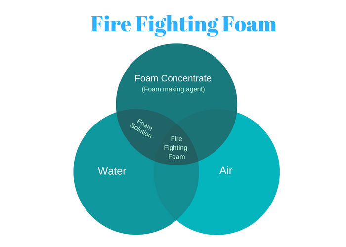
Foam concentrate is mixed with water in a correct proportion to form a foam solution. This foam solution when agitated with air produces foam.
Foam extinguishes the fire in three ways
- It forms a blanket and thus removing the supply of oxygen to the fuel, the effect called smothering.
- The foam blanket does not allow the fuel vapors to generate, thus cutting the fuel supply to the fire
- Since foam has water, it cools the fuel surface
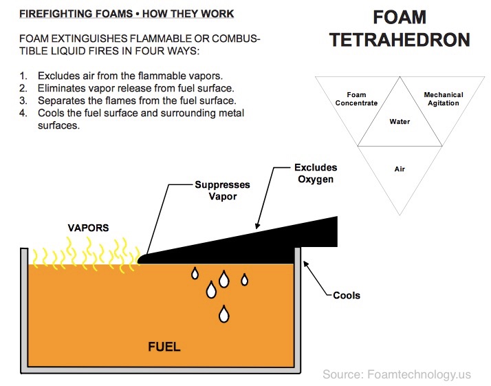
Main terms used in defining the foam
Now let us get to know few of the terms associated with foam.
Expansion ratio
We all understand how a foam solution is formed. The form concentrate is mixed with the sea water and air at the foam monitor causes this foam solution to generate foam.
In other words, foam concentrate that we have in foam room tank expands to generate foam. Different foam concentrate has different capacity of how much foam these can generate from a fixed quantity of foam concentrate.
The ratio of the volume of foam generated (finished foam) to the foam concentrate used in that is called expansion ratio of foam.
The foam with expansion ratio between 1:2 and 1:20 is called low expansion foam.
Foam with expansion ratio between 1:20 and 1:200 is called medium expansion foam.
Foam with expansion ratio above 1:200 is called high expansion foam.
Drainage time
IT is the measure of how quickly a foam solution can move over a surface. Foam solution that has lesser drainage time move faster over a surface.
Drainage time is measured for 25% solution and 50% solution. This is called 25% drainage time and 50% drainage time.
Proportioning rate
Foam is generated by mixing foam concentrate with water. For the effective generation of foam that can be effective in firefighting, a correct amount of water need to be mixed with foam concentrate.
This ratio is called proportioning ratio. It is also called mixing ratio or dilution rate.
So 6% foam concentrate means that the ideal foam solution from this foam needs to have 6 parts of the foam concentrate and 94 parts of water.
Knockdown speed and flow
Knockdown speed and flow is the ability of the foam to flow on the fuel and around the obstacles.
Good knockdown speed would mean that the foam is able to flow past the obstacles on the fuel surface.
Type of Foam solutions used on board ships
Broadly all foams fall under one of these two categories
- Chemical foam
- Mechanical foam
Chemical foam produces the foam by chemical reaction of two chemicals, one being alkali and second an acid.
Mechanical foam uses physical agitation of the foam concentrate to produce foam.
On board ships, the mechanical foam is mostly used. There are different type of mechanical foam used on board depending upon the expected source of the fire.
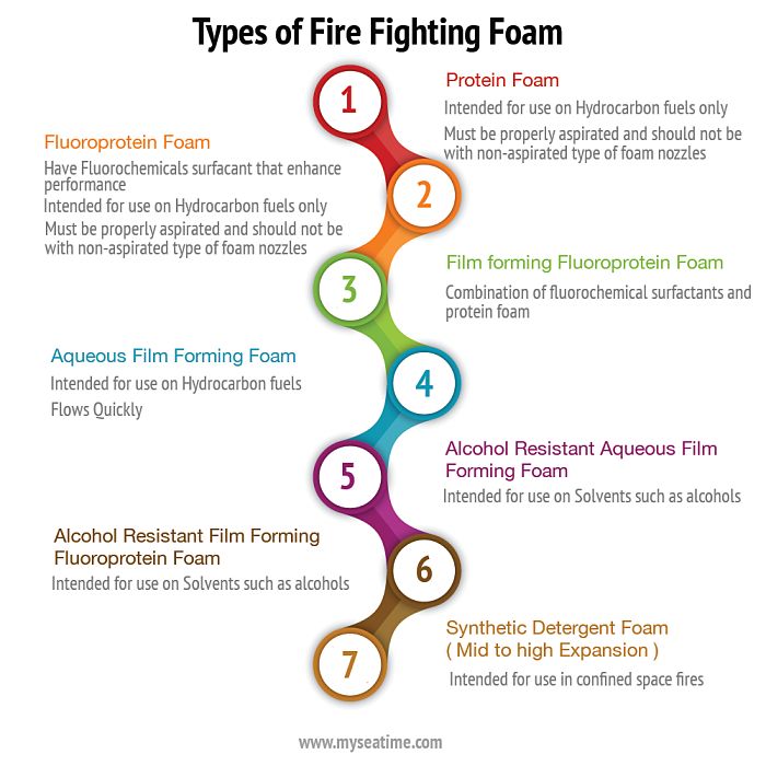
Let us discuss few of these.
Aqueous film forming foam concentrate (AFFF)
This is the very common type of foam used on board ship specially on tankers.
As the name suggests, apart from the foam bubbles, this foam makes an aqueous film over the surface that spreads across the surface of hydrocarbon to extinguish the fire.
These type of foam works on the fires generated from burning of hydrocarbons.
Alcohol resistant Aqueous film forming foam concentrate (AR-AFFF)
As I said foam has water in it. All the solvents like alcohols are miscible in water. So if we use normal foam on alcohol fires, alcohol will dissolve the water and foam will break up easily.
So for extinguishing the fires involving solvents like alcohol, normal foam concentrate will not do.
For fighting the fires involving alcohols and other solvent alchohol resistant foam is required.
On chemical tankers, that have foam as fixed fire fighting system for cargo fires, alcohol resistant foam is a must. This is because these ships carry alcohols (like Methanol, ethanol) as cargo.
So next time we check the foam certificate on a chemical tanker, we must look for the information mentioning the foam to be alcohol resistant.
Foams based upon the expansion ratio
We discussed that there are three types of foams based on the expansion ratio.
- High expansion foams
- Medium expansion foams
- Low expansion foams
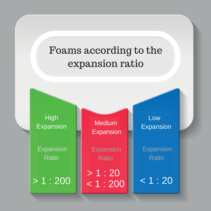
But which foam will be used where ?
Would’t it be the fact that high expansion foams will generate more foam from less foam concentrate and thus be more effective ?
So the high expansion foam is very light and low expansion foam is comparatively heavier.
If we use high expansion foam for deck fires, the foam will fly with the wind and will not be able to extinguish the fire.
For this reason, for deck fires low expansion foam is used. On tankers, it will always be low expansion foam for fires of the cargo area.
High expansion foams are used for compartments such as holds and even machinery spaces where the space need to be filled with foam for fire fighting.
Functioning of Fixed foam system
Below is the basic line diagram of a typical fixed foam system on ships.
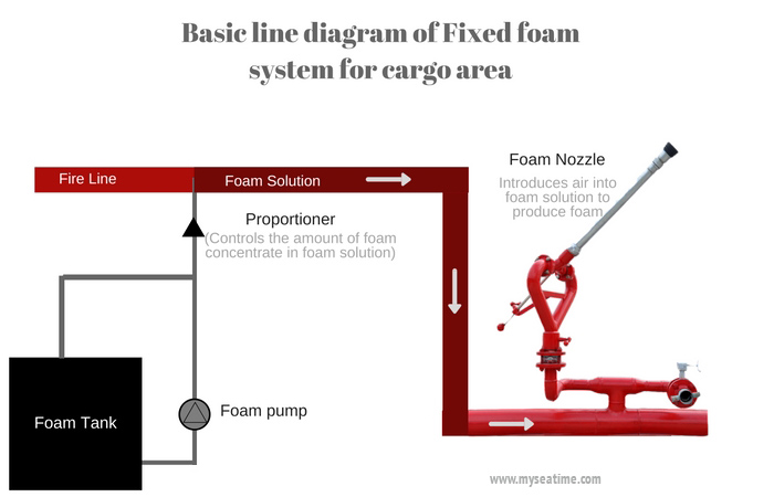
The foam pump takes the foam concentrate from foam tank and injects it in desired ratio into the water. The proportioner controls the quantity of foam solution to inject.
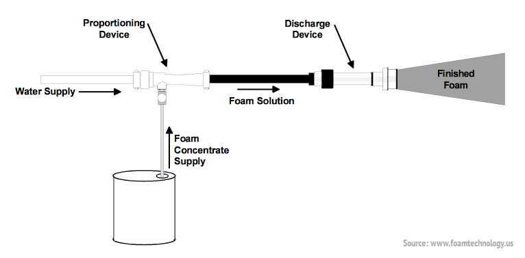
The common type of proportioner is of ejector type. The more the fire line pressure, more foam it will inject. Ship staff are not supposed to touch the proportioner.
When the foam solution reaches foam nozzle on deck, the air is injected into the foam solution to create the fire fighting foam.
The foam so generated creates a layer over the fire and cuts the oxygen supply, the process called smothering to extinguish the fire.
Maintenance required on fixed foam system
There are many components of the fixed foam system such as
- Foam line
- Foam monitor
- Foam isolation valves
- Fire pumps
- foam concentrate (foam solution)
- Foam pump
- foam proportioner
Each one of these need to work as desired. We, the ship staff need to make sure that each one of these are in perfect condition. The only way to ensure that is by testing of all element of foam
i) Testing of foam line, foam monitor and foam isolation valves
If the foam line is leaking, or the foam monitors cannot be turn around to aim the foam at the fire, we would not be able to use the foam system.
Every year the foam line need to be pressure tested at least to the maximum working pressure. We must check the SMS manuals of the ship for any special testing requirements from the company.
The testing procedure would be
- Close all the valves of the fire line and foam line
- Open the foam monitor on the forward most part of the ship
- Start the fire pump at maximum pressure
- Slowly close the foam-monitor that was kept open
- Check for any leakage
Apart from checking the foam line leakage, we also need to check if any foam monitor valve is leaking. For this we just need to check that no foam monitor is leaking when the foam line is pressurised.
If we spot a leaking foam monitor, we must first check if the foam valve is tightly shut. If it is still leaking, we should overhaul the foam valve.
Remember, foam system is a critical equipment. And if we plan to remove the valve for overhaul, we must carry out risk assessment as for the period of the overhaul, the foam system would not be available for use. The company may also require the ship to take their approval before proceeding with this work.
We also need to test if the foam isolation valves are holding.
To test the foam isolation valves
- Keep the forward most foam monitor open
- Close the foam isolation valve one by one and check if the water from the foam monitor stops completely.
ii) Foam pump
We test the foam pump during the fire drill involving fire on deck. The foam pump is run on recirculation. We must make sure that the part of the foam line involved during re-circulation is effectively drained and empty after testing.
iii) Fire pump
Fire pump is an important part of the foam system. It delivers the foam solution to the foam monitors. While testing the fire pumps for foam system, we run the fire pump at full pressure.
We then open the two foam monitors and directs the jets overboard. The jets from these two should be able to cross each other.
iv) Foam concentrate
The main element from which the foam is generated is Foam concentrate stored in the foam tank. We have to check two things for foam concentrate
- Quantity of the foam concentrate
- Quality of the foam concentrate
For the vessels fitted with inert gas system, there need to sufficient foam concentrate for running for 20 minutes at maximum flow rate.
For vessels not fitted with inert gas system, there should be sufficent quanitity of foam concentrate for running for 30 minutes at maximum flow rate of the fire system.
The required quantity is usually marked on the foam tank gauge. We must ensure that this quantity is never below the mark.
With regard to quality of the foam, there is only one way we can know. By analysis of sample of foam
Sample analysis of foam concentrate
SOLAS requires the foam sample to be tested after 3 years from the date it was placed onboard and there after every year.
Various tests are carried out on the foam sample to ensure that the foam is fit for the purpose it is supposed to do. The tests include
Sedimentation Test: Sediments should be less than 0.25%
pH value test: The pH of the foam concentrate should not be less than 6 and not more than 9.5 at 20 Deg C
Drainage time test
Chemical stability test for Alcohol resistant foam:
The alcohol resistant foams are different from other type of foams. Water content from normal foam will dissolve in the solvent and so these forms are not suitable for solvents. Additives in the alcohol resistant foam form a membrane that separates the solvent and foam which avoids the breaking up of the foam blanket.
SOLAS REGULATION FOR FIXED DECK FIRE FOAM IN SHIP :
1)The arrangements for providing foam shall be capable of delivering foam to the entire cargo tanks deck area as well as into any cargo tank, the deck of which has been ruptured.
(2) The deck foam system shall be capable of simple and rapid operation. The main control station for the system shall be suitable located outside the cargo area adjacent to the accommodation paces and readily accessible and operable in the event of fire in the areas protected.
(3) The rate of supply of foam solution (that is, the mixture of foam concentrate and water before expansion) shall be not less than the following whichever is the greatest:
- 0.6 litre per minute per square metre of cargo tanks deck area, where cargo tanks deck area means the maximum breadth of the ship times the total longitudinal extent of the cargo tank spaces.
- 6 litre per minute per square metre of the horizontal sectional area of the single tank having the largest such area; or
- 6 litre per minute per square metre of the area protected by the largest monitor, such area being entirely forward of the monitor, but not less than 1, 250 litres per minute.
(4) Sufficient foam concentrate shall be supplied to ensure atleast 20 minutes of foam generation in ship fitted with an inert gas system complying with solas to these Regulations or 30 minutes of foamgeneration in ships not fitted with an inert gas by system when using the solution rates stipulated in paragraphgraph (3) .
(5) Foam from the fixed system shall be supplied by means of monitors and foam applicators. At least 50 per cent of the foam solution rate required in sub-paragraphs (a) and (b) of paragraph (3) shall be delivered from each monitor. On tankers of less than 4,000 tonnes deadweight, applicators may be substituted for an installation of monitors. In such a case the capacity of each applicator shall be at least 25 per cent of the foam solution rate required in sub-paragraphgraph (a) or (b) of paragraph (3).
(6) (a) The number and position of monitors shall be such as to comply with paragraph (1). The capacity of any monitor shall be at least 3 litres per minute of foam solution per square metre or deck area protected by that monitor, such area being entirely forward of the monitor. such capacity shall be not less than 1,250 litres per minute.
(b) The distance from the monitor to the farthest extremely of the protected area forward of that monitor shall not be more than 75 per cent of the monitor throw in still air conditions.
(7) A monitor and hose connection for a foam applicator shall be situated both port and starboard at the front of the poop or accommodation spaces facing the cargo tanks deck. On tankers of a dead weight of less than 4,000 tonnes not fitted with monitors a hose connection for a foam applicator shall be situated both port and starboard at the front of the poop or accommodation spaces facing the cargo tanks deck.
(8) The capacity of any applicator shall be not less than 400 litres per minute and the applicator throw in still air conditions shall be not less than 15 metres. The number of foam applicators provided in accordance with the requirements of paragraphgraph (5) shall be not less than four. The number and disposition of foam main outlets shall be such that foam from at least two applicators can be directed on to any part of the cargo tank deck area.
(9) Valves shall be provided in the foam main, and in the fire main when this is an integral part of the deck foam system, immediately forward of any monitor position to isolate damaged sections of those mains.
(10) Operation of a deck foam system at its required output shall permit the simultaneous use of the minimum required number of jets of water at the required pressure from the fire main.
System Description


The form pump take suction from foam concentrate foam tank and inject it in desired ratio into the water. The proportional controls the quantity of FOAM solution to inject. The common type of proportional is of ejector type the more the fire line pressure,more form solution will inject. Ship staff are not supposed to touch the proportionar when the form solution reaches form nozzle or foam monitor the air is injected into the foam solution to create the fire fighting foam. The foam so generated creates a layer over the fire and cuts the oxygen supplyto extinguish the fire. If a fire breaks out in enclosed area or vessel, we depend on an extinguishing system that deploys quickly, effective and safe for personal. This system is cost effective and safe for the crew and environment fast and effective solution for machinery spaces fire with filling rate of 1.8 metre per minute the system can be installed as a total flooding system for the entire machinery room or for individual compartment .Quick activation of the system, minimum fire and heat damage to equipment and structure form is not harmful and the cooling effect hinders the fire from ignition after it is extinguish use no hazardous decomposition product that would cause damage . It is formed expansion ratio of 1 :666 at nominal pressure of 6 by using inside air. It uses a synthetic foam concentrate. The system consists of foam generator ,foam Storage tank, foam concentrate ,foam Storage tank at atmospheric pressure, foam pump, form proportionate, distribution pipe made up of galvanized steel ,strainer, valve ,test and blow through lines ,power and control system for optimal effectiveness it is critical that the foam concentrate is mixed with water in the correct proportion throughout the fire fighting operation . Foam generator expand the foam mixture with the use of air drawn from the protected space. The system can be manually released released from the form room by directly operating the valves and Pump it can also be operated by centrally located control cabinet for operational flexibility.
This can can act at an emergency during main power source failure.
-rate of 1 metre per minute
-500 metre cube and above 2000 GRT and above should have a fixed fire fighting system.
-Quantity of form for forming liquid is equal to 5 times volume of largest space to be protected.
-Foam concentrate for 30 minutes.
- A system should be approved by administration
-System shall be capable of manual activation automatic interlock is not permitted unless appropriate interlocks are provided.
-System away from protected space.
-Operating instruction for system shall be displaced at main as well as local control station.
-The foam generator shall be located at the place where adequate fresh air supply can be arranged.
-The arrangements shall be provided for the crew to safely check the quantity of foam concentration.
-Supplied with main and emergency power source.
-Pipeline should not interfere with the access to the installation of machinery for routine maintenance.
-The foam generator room Shall be ventilated to protect against overpressure and shall be heated to avoid the freezing.
.

No comments:
Post a Comment